


 Chinese
 Spanish
 Russian
 Portuguese
 French
 German
 Indonesian
 Thai
 Vietnamese
 Arabic
 Italian
 Turkish
 Polish
 Japanese



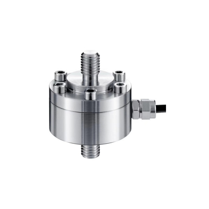
METRAVON MV-LC0113 is a dual-stud tension and compression load cell for axial force fixtures. The stainless-steel diaphragm assembly is documented for loading in both directions over a 50 kg-2 t family. Opposed M12 studs provide the measuring connection; the housing bolts are assembly features, not extra places to attach the load. Plan the sensor and both external couplings as one axial installation.
Reserve coupling space beyond the dual-stud tension and compression load cell body
The reference body is 50 mm in diameter, with a 27 mm body-height designation and 70 mm overall axial length. Both measuring ends are designated M12. The drawing also shows a 14 mm cable-entry projection reference. Add the mating couplings, locking access and cable bend space when assessing the final installation. The M12 label alone does not establish every thread detail, allowable engagement or the rating of hardware borrowed from an old fixture.
| Item | Value | Selection notes |
|---|---|---|
| Family range | 50 kg-2 t | Specify the actual tensile and compressive operating intervals. |
| Stud designation | M12 at both ends | Confirm coupling geometry, engagement and locking arrangements. |
| Body diameter / body height | 50 / 27 mm | Review housing clearance without using assembly bolts as load points. |
| Overall reference length | 70 mm | External couplings and locking parts add to the installation length. |
| Cable-entry projection reference | 14 mm | Reserve additional space for the final protected cable bend. |
| Nonlinearity | +/-0.3-0.5% FS | Hysteresis and repeatability are each +/-0.3% FS. |
| Temperature / protection | -20 to +70 deg C / IP66 | Check the stainless-steel assembly and external wiring exposure. |
Keep the reversing load on the intended axis
Describe the actual tensile and compressive intervals, preload and any joint movement. A linkage that shifts as force reverses can introduce bending even when the stud threads fit correctly. Agree how each coupling is supported and how adjustment is made without twisting the diaphragm assembly. Do not use the sensor cable as a reaction restraint. If a moving joint is needed, assess that attachment with the force cycle instead of assuming the measuring body supplies articulation.
Verify sign and span for the required force directions
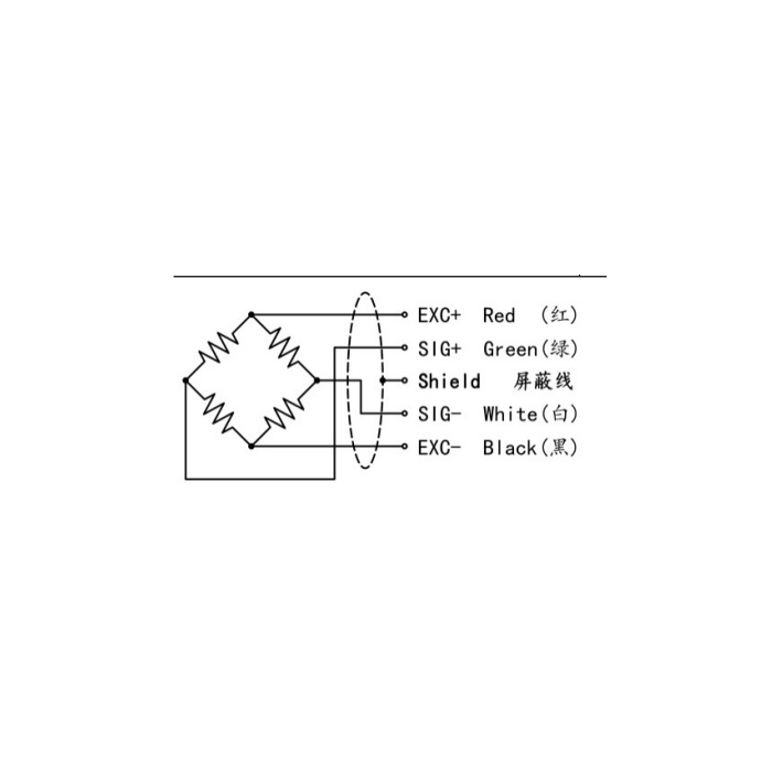
The output entry spans 1.5-2.0 mV/V with a listed +/-0.05 mV/V tolerance; confirm the actual nominal output rather than copying a former sensor gain. The bridge needs 5-12 V DC excitation and lists 750 +/-30 ohms input resistance and 700 +/-5 ohms output resistance. Connect the final 3 m, 5 mm diameter cable and confirm the reader can display the required positive and negative engineering-unit values. A correct tensile reading does not verify compression scaling or sign handling.
Accept the loaded fixture after reversal and release
Apply suitable references in both directions when the process uses both, compare repeated passes near the decision forces and record return after release. The tabulated error characteristics are not a promise of identical whole-fixture errors in every load cycle. The safe-overload entry is 150% FS, unlike the 120% figures of several compression diaphragm designs. It does not establish fatigue life or permission for routine above-capacity cycling.
Axial couplings and bidirectional verification
Q1. Can a floating-plate compression model replace this sensor?
A raised plate does not provide the same tensile force path as opposed studs. If the fixture pulls as well as pushes, retain an explicitly bidirectional measuring arrangement and assess both couplings. Similar diaphragm construction does not establish equivalent attachment or loading capability.
Q2. Can the old M12 fittings be retained automatically?
Compare their full thread details, engagement, alignment, installed span and mechanical rating with the offered assembly. M12 is only one matching feature. Verify the complete fixture and recalibrate after the connection is approved.
Q3. Is one compression calibration sufficient for a push-pull process?
The required tensile and compressive indications both need suitable verification, including sign, repeatability and return after reversal. State those acceptance points before configuring the reader. A single-direction span does not demonstrate the complete reversing-force measurement.
