


 Chinese
 Spanish
 Russian
 Portuguese
 French
 German
 Indonesian
 Thai
 Vietnamese
 Arabic
 Italian
 Turkish
 Polish
 Japanese



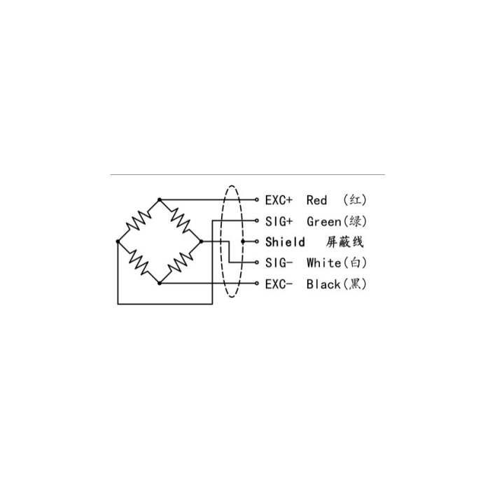
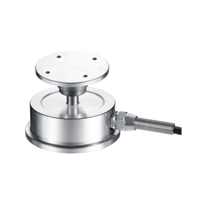
METRAVON MV-LC0112 is a floating-plate diaphragm load cell for compression-force and weighing fixtures. A raised circular plate transfers load to the diaphragm body while leaving space between the loading plate and the main housing. The documented family is 100-500 kg. The term floating identifies this arrangement; it does not establish a swivel joint, an allowed travel or permission to pull the plate sideways.
Keep the floating-plate diaphragm load cell clear of its surroundings
The reference top plate is 48 mm in diameter and 3 mm thick. Overall height is 47 mm, with a 57 mm main-body diameter and a 64 mm base envelope. Include the raised plate and stem in the fixture-clearance review, not only the lower housing. A cover or attached member that contacts the body during loading can create an unintended support and change the reading. Agree the complete compression path before fabricating the fixture.
Treat the top holes as an attachment interface, not a load rating
Four 3.5 mm holes are shown on a 35 mm circle, with a 7 mm counterbore diameter designation. Confirm the mating fastener, engagement and support arrangement from the selected drawing. The hole pattern does not specify the size of a permissible overhanging platform. Submit the actual plate or tooling, its tare and possible contact positions so the resulting force and moment can be assessed. Do not infer tensile capability from the ability to fasten an attachment to the upper plate.
| Item | Value | Selection notes |
|---|---|---|
| Family range | 100-500 kg | Include attached tooling tare and the actual contact positions. |
| Raised plate diameter / thickness | 48 / 3 mm | Review the upper attachment and its clearance from the housing. |
| Total reference height | 47 mm | Allow space for the complete moving or loaded structure. |
| Main body / base envelope | 57 / 64 mm | Do not treat the wider base as an additional loading contact. |
| Top holes / circle | 4 x 3.5 mm / 35 mm | The drawing also designates a 7 mm counterbore diameter. |
| Safe overload | 120% FS | Keep expected working loads within the selected rating. |
Establish a useful reference with the attached tooling installed
The sensitivity entry is 1.0-1.5 mV/V with a listed +/-0.05 mV/V tolerance. Request the actual offered nominal output and use a compatible 5-12 V DC bridge reader. Input resistance is 380 +/-30 ohms and output resistance 350 +/-5 ohms; cable length is 3 m at 5 mm diameter. Compare empty and loaded references after the top attachment and final cable routing are complete. Include relevant contact positions if the tool can load the raised plate differently.
Investigate a changed zero before adjusting the display
If the unloaded reading changes after an attachment or guard adjustment, inspect clearance, retained preload and cable force before altering gain. Repeat the working points after the mechanical condition is resolved. The documented safe overload is 120% FS; nonlinearity is +/-0.3-0.5% FS and repeatability +/-0.3% FS. Specify the required assembled-fixture performance at the working forces. IP66 and -20 to +70 deg C describe the listed sensor conditions, not an approval for every cleaning or process environment.
Raised-plate movement and attachment effects
Q1. Does floating mean the upper plate can tilt or rotate freely?
No permitted tilt, rotation or travel is specified by that name. Provide the proposed movement and contact geometry for assessment. Keep the agreed loading direction and inspect the final clearance rather than using the visible stem as an assumed joint.
Q2. Can the attached platform be pulled upwards during a test?
This version is documented with a compression loading arrangement. Top attachment holes do not establish a bidirectional rating. Where the measurement must reverse into tension, specify a suitable tensile connection and obtain the corresponding model evidence.
Q3. What should be checked if a cover changes the unloaded reading?
Inspect whether it touches the upper plate or stem, changes attachment preload, or pulls on the cable. Restore the intended clearances and compare reference loads again. A new zero setting alone cannot establish that the original force path has been preserved.
