


 Chinese
 Spanish
 Russian
 Portuguese
 French
 German
 Indonesian
 Thai
 Vietnamese
 Arabic
 Italian
 Turkish
 Polish
 Japanese



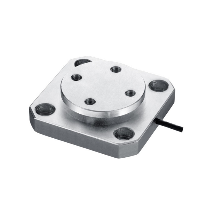
METRAVON MV-LC0111 is a plate-mounted diaphragm load cell for pedal-force and industrial force-test fixtures. The 50 kg-1 t family combines a circular loading plate and square base. The upper plate threads and base clearance holes have different roles in the fixture; copying one bolt pattern onto both mating parts can create an incorrect load path even when the sensor appears to fit.
Separate the loading-plate attachment from the base mounting
The reference outline is 70 by 70 mm and 20 mm thick. The circular upper plate is 50 mm in diameter, with four M6 positions on a 35 mm circle. The base uses four 7 mm clearance holes on a 50 by 50 mm square pattern; counterbores are designated 11 mm diameter and 6.5 mm depth. Identify both interfaces in the assembly drawing and check fastener access. Do not substitute the plate thread pattern for the base pattern or let an external member bear on both parts.
| Item | Value | Selection notes |
|---|---|---|
| Reference base / thickness | 70 x 70 / 20 mm | Check the loaded attachment and cable exit as well. |
| Upper plate / thread circle | 50 / 35 mm | Four M6 positions belong to the loading-plate interface. |
| Base holes / square centres | 7 mm / 50 x 50 mm | Four clearance holes are shown in the base. |
| Counterbore diameter / depth | 11 / 6.5 mm | Verify fastener head and tool clearance on the full drawing. |
| Excitation / cable | 5-12 V DC / 3 m | Cable diameter is 3 mm; identify the bridge supply in the system. |
| Input / output resistance | 380 / 350 ohms | Tolerances are +/-30 ohms input and +/-5 ohms output. |
| Nonlinearity | +/-0.3-0.5% FS | Hysteresis and repeatability are each +/-0.3% FS. |
| Safe overload | 120% FS | Account for approach and handling peaks in the fixture design. |
| Operating temperature / housing | -20 to +70 deg C / IP66 | Choose the offered steel version for the exposure. |
Check what the plate-mounted diaphragm load cell actually supports
Submit the loading attachment, force direction and expected contact positions. A larger attached platen or a pedal adapter can introduce a moment if force arrives away from the intended axis. No unrestricted platform size or eccentric-load rating is established by the four upper threads. Check clearance between the loaded attachment, base and guides throughout movement. Zeroing with the assembly fitted does not correct a bypass that changes under load.
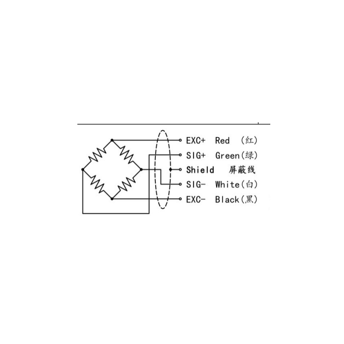
Identify where excitation and force scaling are provided
For a retained acquisition module, identify the bridge supply and where the conversion to force units is stored: in a display, conditioner or controller. An input that can read millivolts does not necessarily provide sensor excitation or a weighing calibration function. MV-LC0111 lists a 1.0-1.5 mV/V sensitivity range with a +/-0.05 mV/V tolerance; obtain the delivered nominal output before approving a saved parameter file. Verify the indicated force with the platen installed, not just the voltage measured at an unloaded terminal.
Use repeat tests that expose attachment movement
Compare selected force points during loading and unloading and note any movement of the platen, guides or retained pedal adapter. Recheck empty indication after release and after the relevant fixture repositioning. Evaluate the error entries against those results rather than judging a fixture from one central load. The 120% FS safe-overload entry does not establish a permitted working excursion. Keep measurement acceptance separate from any machine protective function and specify the required channel response with the acquisition equipment.
Plate attachment and base compatibility
Q1. Is it interchangeable with MV-LC0110 because both bodies are 70 mm square?
MV-LC0110 has a curved contact and side retention, while this model has an upper M6 plate pattern and a four-hole base. Capacity and output options differ too. Compare the complete attachment and reader setup instead of relying on the shared external width.
Q2. Can a large platform be fastened to the four M6 threads?
The threads establish an attachment feature, not a specified platform-size or off-centre-load allowance. Supply the platform dimensions, supported tare, load positions and guiding arrangement for review. Verify the assembled fixture at the required positions after its mechanical suitability is confirmed.
