


 Chinese
 Spanish
 Russian
 Portuguese
 French
 German
 Indonesian
 Thai
 Vietnamese
 Arabic
 Italian
 Turkish
 Polish
 Japanese



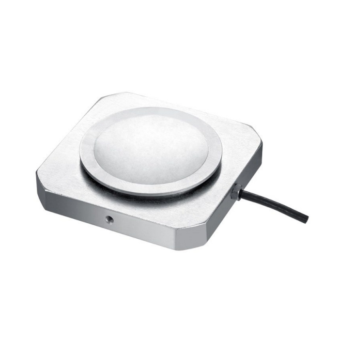
METRAVON MV-LC0110 is a pedal force diaphragm load cell with a curved circular loading surface. It is documented for vehicle braking-force test equipment and other industrial force-measuring fixtures. In a pedal installation, define the measured quantity as the force entering that contact. A pedal-force reading alone is not a wheel braking-force, stopping-distance or hydraulic-pressure result.
Place the pedal force diaphragm load cell in a defined contact path
Provide the pedal face, supporting bracket, contact position and expected pedal travel. The reference body is 70 by 70 mm, with a 20 mm overall thickness designation. Its 54 mm contact is marked SR116. Check whether the applied force remains in the intended direction through the travel and whether the operator or actuator can load the contact differently. The curved face does not establish an unlimited permissible contact angle or remove the need to assess side loading.
| Item | Value | Selection notes |
|---|---|---|
| Family range | 50-200 kg | Choose the actual sensor rating and test-force interval. |
| Reference plan / thickness | 70 x 70 / 20 mm | Check space throughout the intended pedal movement. |
| Contact diameter / radius | 54 mm / SR116 | Review the mating surface and applied force direction. |
| Side retention designation | 2 x M3 | Resolve screw engagement and retention from the drawing. |
| Temperature / housing | -20 to +70 deg C / IP66 | Confirm the offered material and cable exposure. |
| Nominal bridge sensitivity | 1.5 +/-0.05 mV/V | Use a compatible bridge input, not a direct PLC current input. |
| Bridge input / output resistance | 380 / 350 ohms | Input tolerance is +/-30 ohms; output tolerance is +/-5 ohms. |
Retain the sensor without obstructing the pedal movement
Two M3 side fixing positions are shown. Obtain the installation drawing to define retention and engagement rather than fastening a generic strap tightly across the loading face. Include the cable exit and the effect of the added sensor thickness on available movement. A fixture that holds the sensor in one place but allows another member to rub against the loaded plate can alter the force indication. Verify the complete retained assembly, not only the loose sensor on a bench.
Specify the required test result and acquisition channel
The bridge produces 1.5 +/-0.05 mV/V and needs 5-12 V DC excitation. Its cable is listed as 3 m long and 3 mm in diameter. Identify the reader, engineering units, recording interval and any related travel or pressure channel separately. If a test requires peak capture, confirm the complete acquisition response instead of inferring a sampling capability from the sensor capacity.
Compare repeated pedal applications under agreed conditions
Specify contact location, loading method and the force points used to judge the test. Check repeated loading and release after the final retention and cable routing are complete. Nonlinearity is +/-0.3-0.5% FS, while hysteresis and repeatability are each +/-0.3% FS. The listed safe overload is 120% FS, not extra measurement range. Define the allowable spread for the assembled test and inspect contact changes when results depend on how the force is applied.
Compare MV-LC0111 for a bolted loading-plate interface; a shared 70 mm square envelope does not make the mounting interchangeable.
Pedal input force and fixture clearance
Q1. Does pedal force indicate the vehicle braking force directly?
It is an input-force measurement at the defined contact. Wheel braking force and stopping performance involve additional vehicle and test-system relationships. State which quantity is required and obtain the relevant complete test method rather than relabelling the bridge output.
Q2. Can an existing pedal fixture accept the sensor without modification?
Check the additional thickness, pedal travel, contact seating, retention and cable clearance. A matching pedal width is not enough. Compare the assembled motion and reference readings before approving the fixture.
Q3. Which model should be considered when the fixture needs a bolted loading plate?
MV-LC0111 has a different plate interface and base-hole pattern. Review that assembly drawing rather than drilling or clamping this curved contact to imitate it. The two models also differ in range and listed nominal output options.
