


 Chinese
 Spanish
 Russian
 Portuguese
 French
 German
 Indonesian
 Thai
 Vietnamese
 Arabic
 Italian
 Turkish
 Polish
 Japanese



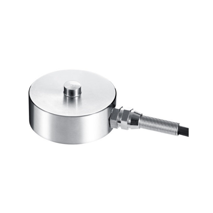
METRAVON MV-LC0109 is a diaphragm compression load cell with a raised central loading button. Its 50 kg-10 t family is intended for industrial force and weighing fixtures that need a relatively low measuring body. Two reference outlines divide the family at 5 t: the larger group changes the contact, mounting circle and body height, so the load rating and fixture drawing must be selected together.
Fit the diaphragm compression load cell below the intended contact
For 50 kg-5 t, the body diameter is 51 mm and total height is 25 mm, with a 10 mm loading contact designated SR50. The 6-10 t group increases the body to 88 mm diameter and 47 mm height, with an 18 mm contact designated SR150. Review the mating tool as a bearing pair, including its approach and any movement. The contact radius is not a statement that the sensor accepts an arbitrary tilt or a contact sliding across the top cover.
Check the underside pattern before reusing a fixture
The smaller group lists four M5 holes, 8 mm deep, on a 42 mm circle. The 6-10 t group uses four M6 holes, 12 mm deep, on a 72 mm circle. An existing fixture may therefore need both a new base and a different upper tool when capacity increases. Confirm thread engagement and the supported surface against the offered drawing. Leave the button and sensing region clear of any cover that could become a second force path.
| Item | Value | Selection notes |
|---|---|---|
| 50 kg-5 t diameter / height | 51 / 25 mm | Top contact is 10 mm in diameter with SR50 profile. |
| 6-10 t diameter / height | 88 / 47 mm | Top contact increases to 18 mm with SR150 profile. |
| Smaller-group base pattern | 4 x M5 on 42 mm circle | Listed thread depth is 8 mm. |
| Larger-group base pattern | 4 x M6 on 72 mm circle | Listed thread depth is 12 mm. |
| Nonlinearity | +/-0.3-0.5% FS | Hysteresis and repeatability are each +/-0.3% FS. |
| Safe overload | 120% FS | Assess mechanical peaks without extending the working range. |
| Temperature / protection | -20 to +70 deg C / IP66 | Confirm steel version and protection at the cable termination. |
Choose the rating for the working interval and foreseeable peak
The safe-overload entry is 120% FS. It does not provide a normal over-range measuring allowance or a machine stopping distance. Include fixture dead load, preload and the peak associated with an approach error in the assessment. Check the error entries against the force decisions the process actually makes; selecting the largest body is not a substitute for evaluating the lowest useful working force.
Verify the button assembly through the final bridge reader
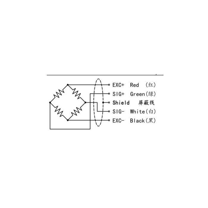
Rated sensitivity is 2.0 +/-0.05 mV/V at 5-12 V DC excitation. The electrical load is 750 +/-30 ohms input and 700 +/-5 ohms output, not a presumed 350-ohm bridge. Complete the listed 3 m, 5 mm diameter cable routing, then compare reference forces through the intended loading tool during approach and release. Record zero return and repeat the decision points used by the machine. Agree dwell conditions separately if the +/-0.1% FS creep entry matters; it has no stated duration here.
Body-group changes and button seating
Q1. Can a 6 t sensor fit where a 5 t body was installed?
The reference changes from 51 to 88 mm diameter, from 25 to 47 mm height and from a 42 to 72 mm fixing circle. The contact profile and thread size change too. Review the complete fixture stack rather than treating the extra tonne as an electronic range change.
Q2. Can force be introduced through the surrounding top cover?
The raised button is the intended compression contact in this arrangement. Submit a different contact proposal for assessment rather than allowing the tool to touch both the button and cover. Reference loading should reproduce the accepted contact path.
Q3. Will setting span remove errors caused by a shifting tool?
A span adjustment establishes gain for one loading condition. It cannot correct a tool that changes seating or rubs against a guide during the cycle. Resolve the contact behaviour and compare repeated loads before accepting the measurement.
