


 Chinese
 Spanish
 Russian
 Portuguese
 French
 German
 Indonesian
 Thai
 Vietnamese
 Arabic
 Italian
 Turkish
 Polish
 Japanese



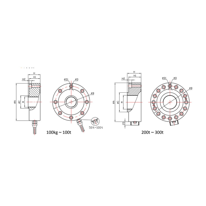
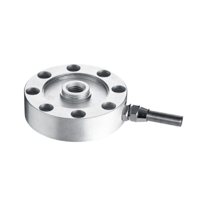
METRAVON MV-LC0108 is a threaded-centre spoke load cell for industrial force and weighing fixtures. Its central attachment and peripheral support pattern change across the documented 100 kg-300 t family. The central thread must be reviewed with the surrounding fixture; its presence alone does not confirm every loading direction, coupling or dynamic duty that a project may require.
Choose the threaded-centre spoke load cell from the exact thread row
At 100 kg-2 t the central thread is M12 x 1.75, with a 75 mm body diameter and 22 mm total-height reference. The 3-5 t group uses M16 x 1.5, while 10-20 t and 30 t both use M32 x 1.5. Even those shared M32 threads do not preserve the body: diameter and height change from 114 and 37 mm to 125 and 45 mm. Review the shoulder, load attachment and adjacent clearances as well as the nominal thread size.
| Item | Value | Selection notes |
|---|---|---|
| 100 kg-2 t central thread | M12 x 1.75 | Body diameter/height are 75/22 mm; fixing circle is 60 mm. |
| 3-5 t central thread | M16 x 1.5 | Body diameter/height increase to 88/34 mm. |
| 10-20 t / 30 t thread | M32 x 1.5 | The two groups have different 114/125 mm diameters and 37/45 mm heights. |
| 50 t / 100 t threads | M40 x 1.5 / M64 x 3 | Peripheral hole count changes from eight to sixteen. |
| 200 t / 300 t threads | M100 x 3 / M130 x 3 | Use the full high-load assembly drawing before specifying mating parts. |
| Cable / temperature | 3 m / -20 to +70 deg C | Listed cable diameter is 5 mm; protect the final termination. |
Allow for changing hole counts and base contact
The 50 t row lists M40 x 1.5, a 148 mm body diameter and eight 11 mm mounting holes on a 125 mm circle. At 100 t the centre becomes M64 x 3 and the outer fixing pattern changes to sixteen 13 mm holes on a 170 mm circle. The 200 and 300 t rows increase further, with M100 x 3 and M130 x 3 centre threads. A central adapter cannot by itself make the smaller base suitable for a larger body; approve the entire support and fastener arrangement.
State the loading direction and assembly duty before ordering
Describe compression, any required tensile measurement, preload, reversals and the actual contact or coupling through the centre. Obtain confirmation for the offered load direction and attachment rather than inferring a bidirectional rating from the thread. Keep the measuring structure clear of external members that could restrain its deflection. For a fatigue or fast-cycle fixture, state the required cycle conditions and acquisition response; no fatigue-life or bandwidth figure is established by the dimensional table.
Match the delivered bridge and verify the final force indication
The nominal output is 2.0 +/-0.05 mV/V at 5-12 V DC excitation. Listed resistance options are 750 +/-30 ohms input and 700 +/-5 ohms output, or 1450 +/-50 ohms input and 1400 +/-5 ohms output. Confirm the actual circuit and the IP65 or IP66 version on the offer. Calibrate through the approved centre attachment with the final support installed, using reference points relevant to the process. The +/-0.05-0.1% FS nonlinearity entry does not include every coupling and support effect.
Thread match and complete fixture compatibility
Q1. Will a 30 t body fit a fixture made for the 10-20 t group?
Both list M32 x 1.5, but body diameter increases by 11 mm and height by 8 mm. The peripheral pattern and supporting surface also need a complete drawing check. Do not approve the replacement from the centre thread alone.
Q2. Does the central thread automatically approve tensile testing?
It is an attachment feature, not sufficient evidence of the offered measuring direction or the strength of the complete pulling fixture. Submit the tensile duty and coupling arrangement for confirmation. Verify the required direction with appropriate references after the assembly is approved.
Q3. What information prevents an incomplete replacement quotation?
Provide the existing capacity, full central thread, peripheral hole pattern, support section, required force directions and reader resistance limits. Include the enclosure version and surrounding cable space so that a similar-looking body is not offered as an unsupported direct replacement.
