


 Chinese
 Spanish
 Russian
 Portuguese
 French
 German
 Indonesian
 Thai
 Vietnamese
 Arabic
 Italian
 Turkish
 Polish
 Japanese



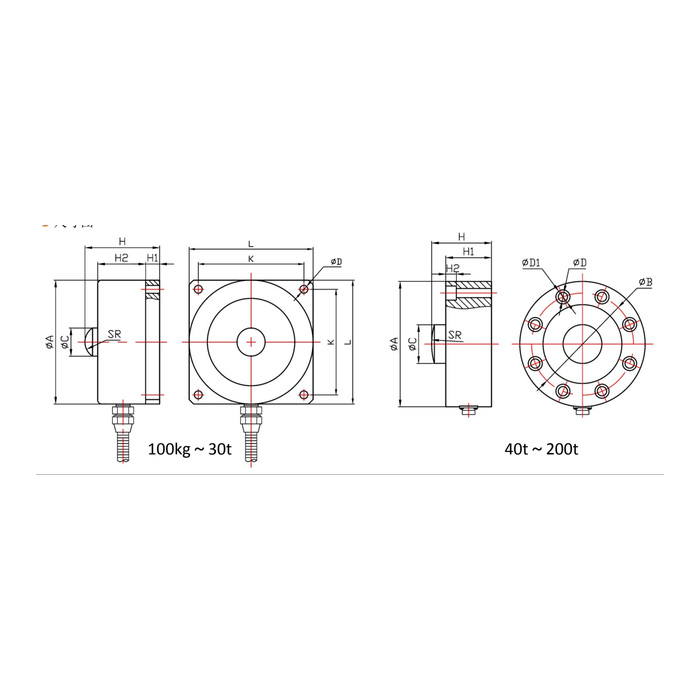
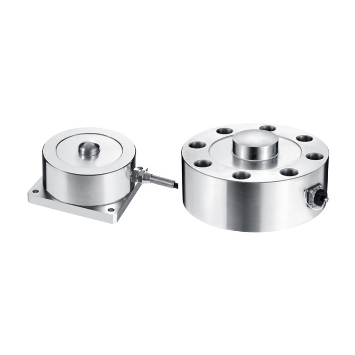
METRAVON MV-LC0107 is a button-top spoke load cell for compression-force and weighing fixtures. Its central contact receives the load while the outer structure is supported by the fixture base. Lower-capacity and higher-capacity outlines use different mounting arrangements. Select the contact and the support together rather than describing every round spoke sensor as mechanically interchangeable.
Confirm the capacity drawing, especially above 200 t
The family specification lists 100 kg-500 t, but the available dimensional rows extend only through 200 t. An exact offered drawing and supporting specification are needed above that point; dimensions must not be extrapolated from the 200 t body. The lower outline covers 100 kg-30 t with a square-base pattern, while the illustrated 40-200 t arrangement uses a circular mounting pattern. Confirm the intended assembly before assuming that a larger nominal rating preserves the old mounting method.
Match the button-top spoke load cell base and loading tool
The 100-700 kg row gives a 72 mm body diameter, 41 mm height and 16 mm contact diameter. At 1-8 t these become 88, 53 and 20 mm. The corresponding square fixing centres are 62 and 75 mm. In the circular-base group, 40-50 t uses four 13 mm fixing holes on a 124 mm circle, while 60-80 t uses eight 13 mm holes on a 145 mm circle. Review counterbores, supporting faces and the contact profile with the complete drawing rather than checking hole diameter alone.
| Item | Value | Selection notes |
|---|---|---|
| 100-700 kg diameter / height | 72 / 41 mm | Contact diameter is 16 mm; square fixing centres are 62 mm. |
| 1-8 t diameter / height | 88 / 53 mm | Contact diameter is 20 mm; square fixing centres are 75 mm. |
| 40-50 t diameter / height | 148 / 88 mm | Four 13 mm holes on a 124 mm circle; 20 mm counterbores. |
| 60-80 t diameter / height | 178 / 85 mm | Eight 13 mm holes on a 145 mm circle; 20 mm counterbores. |
| 200 t diameter / height | 260 / 110 mm | Confirm the 90 mm contact and complete mounting pattern. |
| Working temperature | -20 to +70 deg C | Include support, cable and reader conditions in the site review. |
Resolve the bridge resistance and enclosure version on the offer
Two electrical sets are listed: 750 +/-30 ohms input with 700 +/-5 ohms output, or 1450 +/-50 ohms input with 1400 +/-5 ohms output. Both are associated with a nominal 2.0 +/-0.05 mV/V output and 5-12 V DC excitation. Confirm which bridge is supplied, particularly when retaining an indicator or connecting several supports. IP65 and IP66 are listed as versions, not a combined protection rating that every delivered body automatically satisfies.
Apply the reference through the intended central contact
Show the upper tool or vessel support and the way lateral movement is restrained. Do not assume an unrestricted offset-load allowance from a qualitative resistance-to-offset description. Compare suitable compression references at the operating forces and inspect whether the tool seats differently after release. The listed nonlinearity is +/-0.05-0.1% FS and the cable is 3 m long at 5 mm diameter. A top button and peripheral fixings do not establish an approved tensile link or a multi-axis force output.
Review MV-LC0108 when the assembly calls for a central threaded load interface rather than this raised loading button.
Drawing coverage and bridge-version checks
Q1. Does the 500 t family entry include a usable installation drawing?
The dimensional table available here ends at 200 t. Request the exact higher-capacity configuration and drawing before specifying the foundation, loading cap or instrument range. A family heading alone is not a complete quotation or installation basis.
Q2. Can an old indicator be retained because both sensors say 2 mV/V?
Check the delivered resistance set, excitation requirements, capacity and input scaling as well as nominal sensitivity. Compare the final wiring and reference loads after the mechanical installation is accepted. The two listed resistance sets must not be silently treated as one circuit.
Q3. Can a threaded-centre spoke model use the same loading tool?
MV-LC0108 has a different central interface and mounting family. Compare the actual contact or thread arrangement and selected-capacity drawing. A shared spoke principle does not make the button tool and threaded connection equivalent.
