


 Chinese
 Spanish
 Russian
 Portuguese
 French
 German
 Indonesian
 Thai
 Vietnamese
 Arabic
 Italian
 Turkish
 Polish
 Japanese



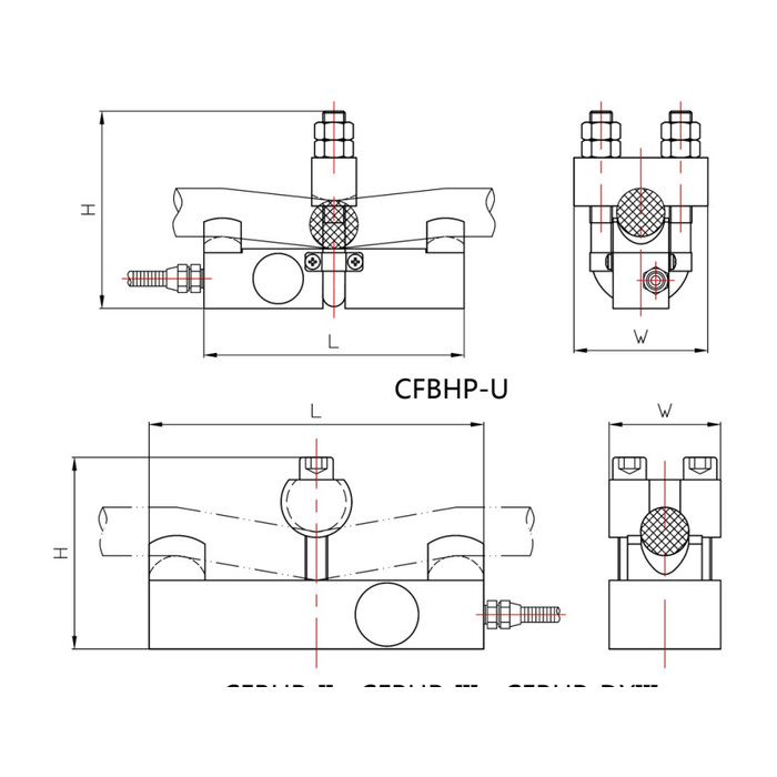
METRAVON MV-LC0117 is a side-force wire rope tension sensor for industrial load display and monitoring systems. It applies a defined contact arrangement to the rope and measures the associated reaction. The documented family covers 1-30 t across several layouts. Select the layout using rope diameter and installation space as well as tension; a family maximum does not establish that every rope fits every assembly.
Match the side-force wire rope tension sensor to the rope construction
Provide nominal and measured rope diameter, construction, condition and the available straight section. Describe whether the rope moves relative to the contacts and identify nearby bends, terminations or obstructions. Contact spacing and imposed deflection affect the relationship between rope tension and the measured reaction. Confirm the selected rope and sensor arrangement together instead of assuming an existing calibration remains valid after changing rope diameter or construction.
Resolve the layout before reserving the mounting envelope
The compact 1-5 t arrangement lists 6-26 mm rope and a 140 by 65 by 110 mm L/W/H reference. Another 1-10 t arrangement lists 6-24 mm rope and 180 by 60 mm L/W, with an 85-110 mm height reference. The 10-20 t and 15-30 t layouts use larger rope ranges and bodies. These overlapping capacity descriptions identify different assemblies, not interchangeable clamps. Obtain the exact drawing and permitted rope/load combination for the offer; height references alone are not a specified adjustment procedure.
| Item | Value | Selection notes |
|---|---|---|
| Compact 1-5 t layout | 6-26 mm rope | Reference L/W/H: 140/65/110 mm. |
| 1-10 t layout | 6-24 mm rope | Reference L/W: 180/60 mm; H is listed as 85-110 mm. |
| 10-20 t layout | 20-40 mm rope | Reference L/W: 200/84 mm; H is listed as 110-140 mm. |
| 15-30 t layout | 30-50 mm rope | Reference L/W: 220/94 mm; H is listed as 110-150 mm. |
| Cable / working temperature | 3 m / -20 to +70 deg C | The listed cable diameter is 5 mm. |
| Housing protection | IP66 | Confirm material and field connections for the actual site. |
Identify the bridge circuit before retaining the controller
The family output entry is 1.0-2.0 mV/V with a listed +/-0.05 mV/V tolerance. Two bridge resistance sets appear: 380 +/-30 ohms input with 350 +/-5 ohms output, or 750 +/-30 ohms input with 700 +/-5 ohms output. Confirm the supplied version and 5-12 V DC excitation with the reader. A raw bridge does not establish an included overload controller, relay, 4-20 mA transmitter or communication interface. List the required acquisition and alarm components explicitly.
Validate rope tension before interpreting machine load
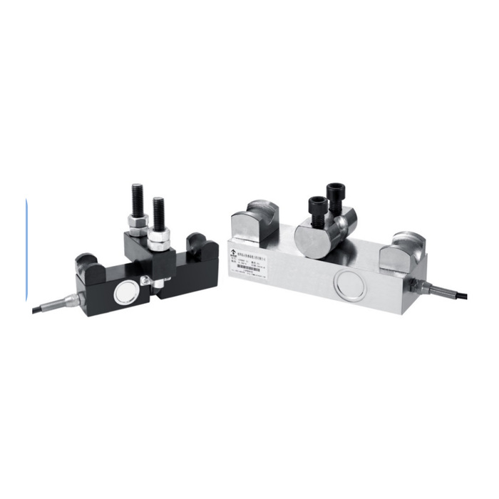
Use the approved assembled rope path and suitable reference conditions to establish the displayed tension. For a reeved lifting system, rope tension is not automatically the hook load: the reeving arrangement and relevant mechanical effects need a defined relationship. Check repeat readings after the agreed installation or adjustment procedure and compare the required operating points. Nonlinearity is listed at +/-0.3-0.5% FS, with +/-0.3% FS hysteresis and repeatability. Do not use a plausible display alone to approve a lifting protection function.
Rope changes, reeving and controller scope
Q1. Can one calibration be retained after fitting a different rope?
Changes to diameter, construction, stiffness or the contact arrangement can change the tension-to-reaction relationship. Review the approved sensor setup and repeat the appropriate references after the rope change. Do not retain a scale factor solely because the new rope has the same nominal load class.
Q2. Does the indicated tonne value equal the load on the hook?
Not without a validated conversion for the lifting arrangement. The device monitors a rope condition, while hook load depends on the relevant reeving and mechanical relationships. Define whether the display is rope tension or an interpreted machine load, then verify that quantity.
Q3. Is an overload safety controller included?
The specification establishes a bridge sensor, not a complete approved safety system. Identify the controller, power, wiring, alarm logic and required application evidence separately. Acceptance must address the entire monitoring or protective function rather than the sensor housing alone.
