


 Chinese
 Spanish
 Russian
 Portuguese
 French
 German
 Indonesian
 Thai
 Vietnamese
 Arabic
 Italian
 Turkish
 Polish
 Japanese



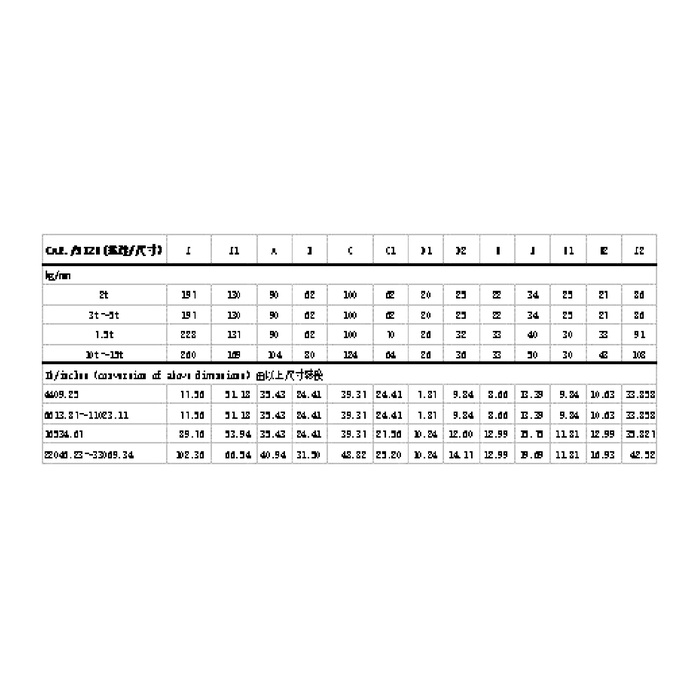
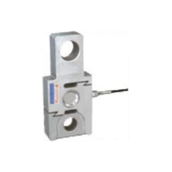
METRAVON MV-LC0089 is a two-eye tension load cell with different hole references at its two ends. It is intended to sit between pinned force members, with the pulling force passing through the measuring body. The detailed capacity entry is 2-15 t. A replacement enquiry should identify the upper and lower attachments separately: assuming equal pin sizes can produce a link that cannot be assembled or that bears incorrectly in its joints.
Check both bores on the two-eye tension load cell
The 2 t and 3-4 t metric rows show D1 at 20 mm and D2 at 23 mm. In the 7.5 t row, D1 remains 20 mm while D2 is 32 mm; the 10-15 t row shows D1 at 20 mm and D2 at 30 mm. The larger-end bore therefore does not increase in a simple progression across the reference groups. Do not select the pin from the nearest capacity or use a common pin for both ends. Request the exact row and full toleranced bore specification for the offered rating.
| Item | Value | Selection notes |
|---|---|---|
| 2 t / 3-4 t D1 and D2 | 20 / 23 mm | Two unequal bores require individually matched joints. |
| 7.5 t D1 and D2 | 20 / 32 mm | Do not carry this larger bore into a different capacity row. |
| 10-15 t D1 and D2 | 20 / 30 mm | Confirm the offered pin fit and tolerances. |
| 2-4 t / 7.5 t L1 | 130 / 131 mm | Include the complete joints and adjustment in the assembly length. |
| 10-15 t L1 | 169 mm | Review guard clearance and mechanism travel after the change. |
| Safe load limit | 200% FS | This is not a working-load rating for pins or the complete link. |
Compare joint-centre distance before retaining the surrounding mechanism
The L1 reference is 130 mm in the 2 t and 3-4 t rows, 131 mm at 7.5 t and 169 mm in the 10-15 t group. Include both external clevises, any adjustment and the travel needed to release the load. A longer assembly may move a guard or cable into contact even where the pin diameters can be matched. Keep the central circular cover and slotted measuring regions out of contact with external supports; their proximity to the attachments does not make them extra mounting faces.
Budget the measurement requirement at the useful force
The listed precision is 0.3% FS, and the temperature-effect entry is 0.3% FS per 10 deg C. A full-scale-related figure is not the same percentage of every small operating reading. Provide the useful force interval, allowable error at the decision points and expected temperature changes before choosing a higher rating for extra mechanical margin. Verify the completed pinned assembly at those forces; pin friction or a changing side load is outside a simple comparison of nominal sensor ratings.
Choose the conditioner and acceptance sequence with the link
Use 10-12 V DC bridge excitation with the specified 2.0 +/-0.015 mV/V output. The reference input and output resistances are 380 +/-5 and 350 +/-2 ohms. Confirm the wiring supplied with the unit rather than selecting signal polarity from inconsistent colour references. For PLC or data-logger integration, identify the bridge reader and any subsequent current or digital output separately. Record tensile loading and unloading references through the final pins before accepting the engineering-unit scale.
An existing single lug at one end may call for a different connection layout. The MV-LC0087 clevis-and-eye link provides a geometry to compare, not an interchangeable part; verify both complete joint assemblies.
Unequal bores and replacement geometry
Q1. Can the two pins be supplied with the same diameter?
The reference rows distinguish D1 from D2, so equal pins are not the default arrangement. Submit both joint designs and obtain a confirmed complete connection. Do not machine the sensor bore or insert an improvised sleeve to make an unreviewed pin fit.
Q2. Is the larger capacity simply a stronger version of the same link?
The bore and joint-centre references change between groups. Check the geometry, useful force resolution and final acceptance points as well as strength. A larger nominal rating alone does not demonstrate interchangeability.
Q3. Does the model include CAN or wireless communication?
The detailed data used here defines an analogue bridge, not a complete bus device. A general family description cannot identify installed electronics or a protocol. Request the exact electrical option and its documentation if the project needs anything beyond the bridge signal.
