


 Chinese
 Spanish
 Russian
 Portuguese
 French
 German
 Indonesian
 Thai
 Vietnamese
 Arabic
 Italian
 Turkish
 Polish
 Japanese



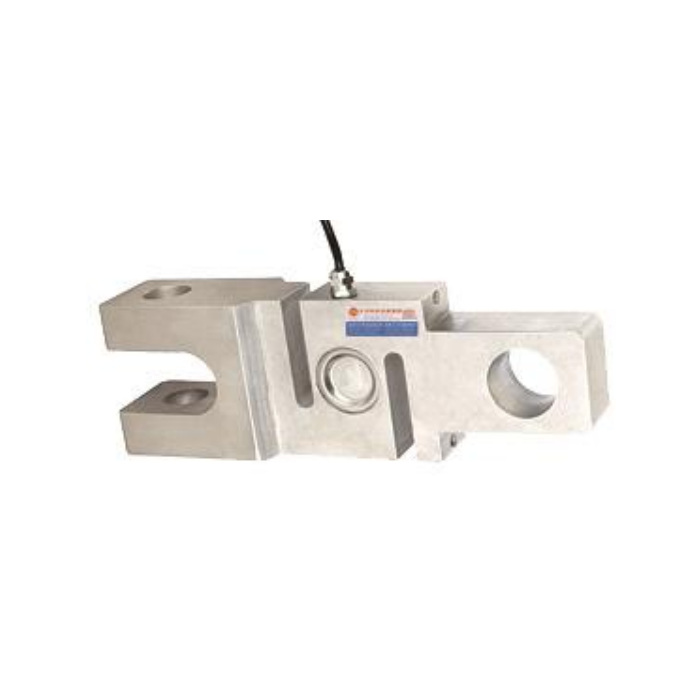
METRAVON MV-LC0087 is a clevis-and-eye tension load cell for an in-line pulling connection. One end is forked and the other has a single eye, so the two attachments cannot be specified by one pin diameter alone. The detailed technical panel lists 2-15 t; a broader family description is not confirmation of every rating or electronic interface. Order one defined mechanical and electrical version with its matching drawing.
Define both joints on the clevis-and-eye tension load cell
At the forked end, identify the mating lug thickness, clevis opening, pin bearing length and retention arrangement. At the eye end, show the surrounding fork, pin diameter and space for articulation. The axial distance between the joint centres must also fit the mechanism. Include a side view of both connections rather than sending only a front photograph. The measuring slots and central cover should remain clear of guards and other members throughout the pulling movement.
Use the dimensional group that belongs to the selected rating
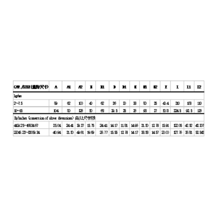
The metric reference separates 2-7.5 t and 10-15 t groups. For example, the D reference changes from 25 to 33.5 mm, so retaining a pin from the smaller group is not a valid default for the larger one. Confirm the complete pin, eye and clevis dimensions with the delivered drawing, including any tolerances and bearing arrangement. The table identifies body groups; it does not certify a pin, shackle or fabricated link as part of an approved lifting assembly.
| Item | Value | Selection notes |
|---|---|---|
| Detailed capacity entry | 2-15 t | Confirm the exact rating rather than applying the broader family text. |
| 2-7.5 t D reference | 25 mm | Match the relevant eye and mating pin drawing. |
| 10-15 t D reference | 33.5 mm | The larger group cannot inherit the smaller pin definition. |
| Rated output / excitation | 2.0 mV/V / 10-12 V DC | The output tolerance is +/-0.015 mV/V; identify any separate electronics. |
| Listed precision | 0.3% FS | A system-level force or protection requirement needs its own acceptance method. |
| Operating temperature | -40 to +85 deg C | Check the joints, connector and conditioner for the same exposure. |
Specify the signal at the sensor-to-controller boundary
The detailed electrical values describe a 2.0 +/-0.015 mV/V bridge with 10-12 V DC excitation, 380 +/-5 ohms input resistance and 350 +/-2 ohms output resistance. General family descriptions also mention current, bus and wireless solutions, but they do not identify the configuration supplied for this quotation. For a PLC current input, request a suitable signal conditioner and its confirmed range. A bus requirement needs the actual interface and communication documentation, not an assumption based on the family introduction.
Separate useful tension measurement from an overload-protection function
Describe whether the signal is used for an operator display, process logging or a protection decision. State the expected slack-to-tension events and where transient peaks must be captured. The precision entry is 0.3% FS; no sampling rate, bandwidth or protection-system performance is established by that entry. A project requiring a protective action must assess the complete sensing, logic and final-action chain. The 200% FS safe-load figure is not an operating allowance for repeated shock loads.
If both existing joints are external clevises, review the MV-LC0089 two-eye arrangement instead of assuming a forked sensor end will fit. Its unequal end bores still require an individual pin check.
Pinned-link installation and signal choices
Q1. Does the fork permit the link to be loaded at an angle?
A fork provides a connection geometry, not a documented off-axis measurement allowance. Show the angular movement and mating parts for review. Prevent binding or side contact rather than assuming that the pin joint removes every bending load.
Q2. Can the sensor connect directly to a 4-20 mA input?
The detailed version documented here has a millivolt-per-volt output. A current-loop installation needs a confirmed conditioned version or a separate converter with excitation and calibration. Specify that equipment on the quotation instead of assuming it is inside the body.
Q3. What should be tested after the pins are installed?
Use agreed tensile references with the actual pins and adjacent links fitted. Check sign, loaded repeatability and the return after release, and inspect for contact during articulation. If peak capture is required, validate the acquisition chain against a defined event as well as the static references.
