


 Chinese
 Spanish
 Russian
 Portuguese
 French
 German
 Indonesian
 Thai
 Vietnamese
 Arabic
 Italian
 Turkish
 Polish
 Japanese


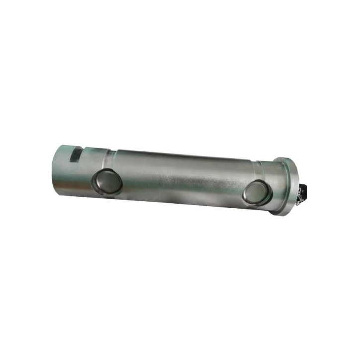

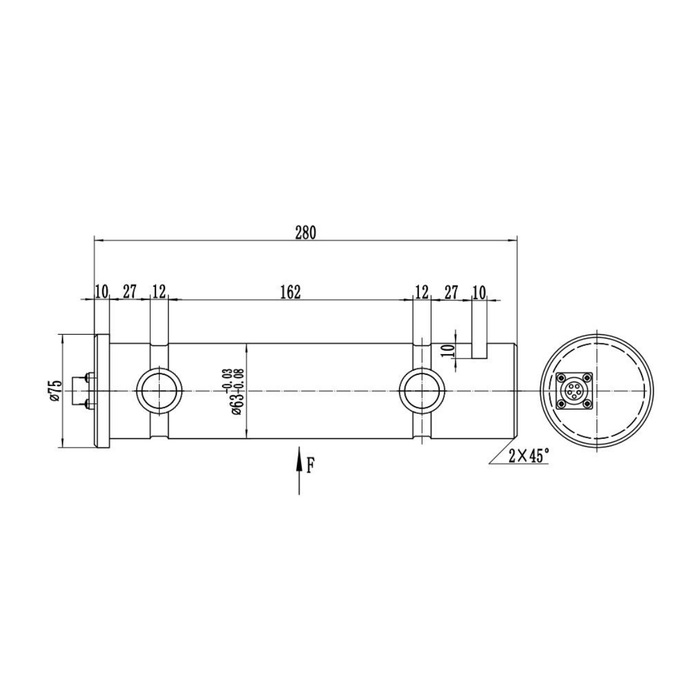
METRAVON MV-LC0014 is a load pin with a 280 mm longitudinal outline and a technical maximum reference of 50 t. The drawing pairs a diameter-63 bearing reference with a 162 mm internal dimension, making the actual joint layout a necessary part of selection. An extended pin is not permission to use any support spacing. Confirm the rated contact arrangement and the direction of the measured reaction before releasing the joint design.
Read the extended load pin drawing as a dimension chain
The 280 mm reference spans the illustrated body arrangement. Further callouts include a diameter-75 end feature, the 162 mm internal reference, two 12 mm sections and local 27 mm dimensions near the ends. These labels refer to separate surfaces and sections. Compare them with the member widths, spacers, insertion path and end clearances on a sectioned assembly. Do not call the whole length a free bearing span or machine a bracket directly from a scaled website image.
| Item | Value | Selection notes |
|---|---|---|
| Technical maximum reference | 50 t | Do not transfer this rating to an arbitrary unsupported length. |
| Longitudinal outline | 280 mm | Add the actual mating connector and service clearance. |
| Bearing / end-feature references | 63 / 75 mm diameters | Require the controlled fit and contact-face definition. |
| Internal dimension | 162 mm | Interpret its datums on the complete approved drawing. |
| Relieved sections | Two 12 mm references | Keep contact widths away from unapproved sections. |
| Reference bridge signal | 1.0 +/-0.015 mV/V | Check the required resolution at the selected rated load. |
Keep force direction separate from the installation viewpoint
The outline places the F arrow below the body, directed upwards. The photograph presents the pin from a different viewing angle. Establish the delivered orientation marks and approved restraint relative to the actual reaction, rather than taking the screen orientation of a photograph as the installation instruction. Show how the joint moves throughout operation. Rotation of the sensing pin, a change of contact position or unintended axial clamping needs review if it alters the measurement condition.
Check the useful measurement interval before accepting the nominal maximum
The reference precision is 0.5% FS and temperature effect is 0.5% FS per 10 deg C. Consider the smallest force change of interest, the selected rating and the temperatures at the pin, not just the peak load. Define how the joint reaction becomes the displayed process value and whether that conversion changes with position. If the reader is expected to report payload, provide the mechanism geometry; do not label the measured reaction as payload without that relationship.
Plan the connector and reader around one selected output
The end-face connector needs access beyond the mechanical outline for its mating plug and cable route. Specify a 1.0 +/-0.015 mV/V bridge with 10-12 V DC excitation only where the reader supports it. The 4-20 mA alternative has a 24 V DC reference, and the CANopen options need their own connection and controller records. A shared housing shape does not establish a common pinout. Ask for both the electrical build and mating-face terminal view with the offered mechanical drawing.
Confirm repeat response at the operating positions
Use independent agreed loads through the installed arrangement and compare the displayed values at the mechanism positions that matter to the project. Record the orientation restraint and the final supporting contacts with the calibration data. Choose material and connection protection for the joint environment; the published operating interval is -40 to +85 deg C and the sealing reference is IP67. The 200% FS safe-load entry does not validate a wider span or an overload test of the surrounding structure. A safety-related installation needs additional system documentation, not just a CANopen Safety option name.
For the 60 mm land reference, see MV-LC0012 bore and bush checks. The two products have different dimensions and technical ratings, so compare their joint drawings rather than treating them as interchangeable pins.
Outline length, force orientation and small load changes
Q1. Can a longer bracket use the full 280 mm as its support span?
That dimension is an outline reference, not a permissible span specification. Submit the bracket section and obtain the rated positions and widths of all load-bearing contacts.
Q2. Is the upward F arrow an instruction to mount the photographed connector on one particular side?
The drawing arrow defines force relative to the illustrated body features. Confirm orientation marks, connector access and the real joint reaction on the supplied drawing; photograph viewpoint alone does not resolve that relationship.
Q3. Does the 50 t reference make the pin suitable for very small load changes?
Assess the useful change against full-scale precision, temperature effect and reader performance. A high nominal maximum does not by itself establish the required low-load resolution.
