


 Chinese
 Spanish
 Russian
 Portuguese
 French
 German
 Indonesian
 Thai
 Vietnamese
 Arabic
 Italian
 Turkish
 Polish
 Japanese


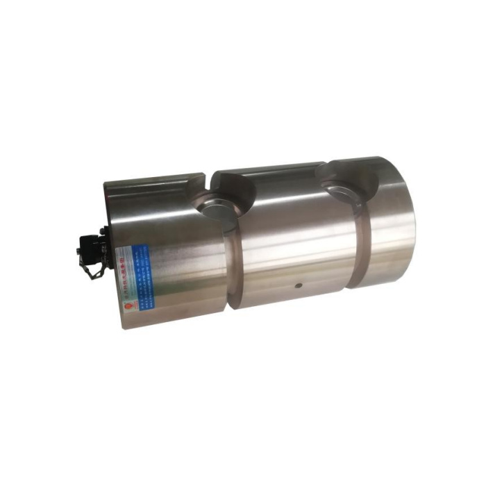

METRAVON MV-LC0013 is a 30 t-reference load pin with three nominal diameter-110 lands and a 225 mm longitudinal outline. Its drawing includes end-face threaded holes and additional passage details, so an enquiry needs more than the bearing diameter. Define the retention, any required service connection and the available end access on the joint drawing. Do not assign a function or load capacity to a hole solely from its appearance.
Identify the end-face features before designing the keeper
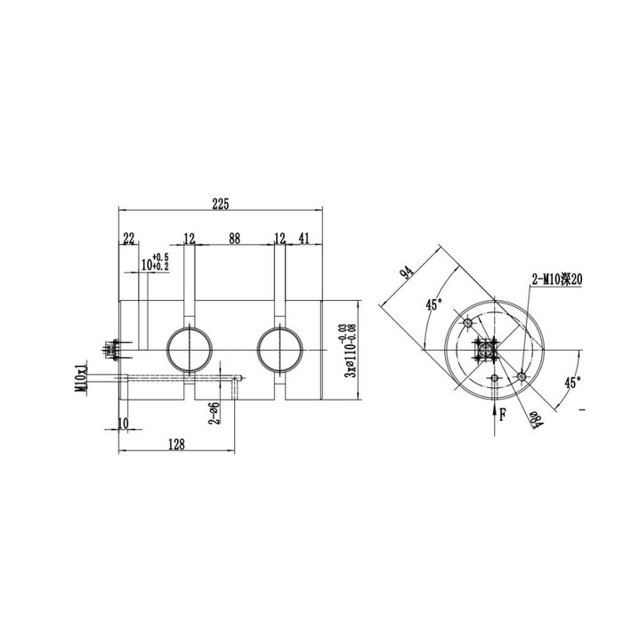
Two M10 holes with a 20 mm depth callout appear in the end view, alongside angular and location references. The longitudinal view also contains an M10 x 1 entry and two diameter-6 passage callouts. Obtain the released drawing and instructions identifying their functions, allowed attachments and sealing. These details do not establish an approved lifting point, a general-purpose mounting pattern or permission to drill an additional hole. A keeper or service fitting must not obstruct the electrical connector or alter the intended bearing contacts.
| Item | Value | Selection notes |
|---|---|---|
| Technical load reference | Up to 30 t | Confirm force direction and the rated support drawing. |
| Longitudinal / central references | 225 / 88 mm | Keep bearing and relieved-section locations distinct. |
| Bearing lands | Three 110 mm diameters | Use the released tolerances and mating fit. |
| End-face threads | Two M10, depth 20 mm | Require the approved function and attachment instructions. |
| Additional drawing details | M10 x 1 and two 6 mm passages | Do not infer a lifting or maintenance function from the labels. |
| Reference precision | 0.5% FS | Installed performance also depends on the final joint and reader. |
Place the diameter-110 load pin on its approved contact regions
The outline gives a 225 mm longitudinal dimension, an 88 mm central reference, two 12 mm relieved sections and three diameter-110 lands with negative tolerances. Record the loaded-member and support widths against those datums. Distinguish contact faces from grooves and end hardware. Where the old assembly has spacers or worn bushes, include their actual dimensions rather than assuming the replacement can carry force at any point along the 225 mm body. Have the final joint arrangement reviewed for the required reaction.
Reserve access for installation and later service
Show how the pin is inserted and withdrawn, where the connector is reached and which parts must be supported during removal. If the application requires a lubrication or service route through the joint, identify it explicitly and have the relevant passage and fitting approved. The outline is not a maintenance instruction. A service arrangement that is inaccessible after installation can make routine work require unsafe or extensive disassembly; settle access and isolation procedures before the fixture is fabricated.
Choose a signal build with a defined terminal schedule
Bridge sensitivity is listed as 1.0 +/-0.015 mV/V at 10-12 V DC. The separate 4-20 mA entry specifies 24 V DC, while CANopen and CANopen Safety appear as alternatives. Select the configuration that the receiving indicator or controller can use and obtain its connector schedule. The front and rear views of a socket are not interchangeable wiring views. Where channel independence is required, request the actual delivered architecture; the general option list does not demonstrate redundancy or safety-function approval.
Test force response after retention and service fittings are complete
Accept the final mechanical state, including the keeper and approved fittings, using agreed load references. Record loaded response, return after unloading and any position dependence relevant to the mechanism. The reference precision and temperature effect are 0.5% FS and 0.5% FS per 10 deg C respectively. Check the specified -40 to +85 deg C interval and IP67 against the pin location and completed connections. Do not use the 200% FS safe-load entry as permission to proof-load the connected machine or its retaining hardware.
Threaded features, service passages and keeper clearance
Q1. Can the two M10 holes carry a lifting eye or extraction tool?
The displayed thread size and depth do not provide a permissible attachment load. Obtain the designated function and an approved tool or handling procedure before using those holes for lifting or removal.
Q2. Are the smaller passage details an instruction to connect grease?
No connection instruction follows from the outline alone. Submit the service requirement and obtain the confirmed route, fitting, sealing and maintenance procedure for the supplied version.
Q3. What if the keeper covers the connector?
Revise the reviewed installation so that retention and electrical service can both be completed. Do not move the pin or supporting bush to an unapproved contact region simply to recover connector access.
