


 Chinese
 Spanish
 Russian
 Portuguese
 French
 German
 Indonesian
 Thai
 Vietnamese
 Arabic
 Italian
 Turkish
 Polish
 Japanese


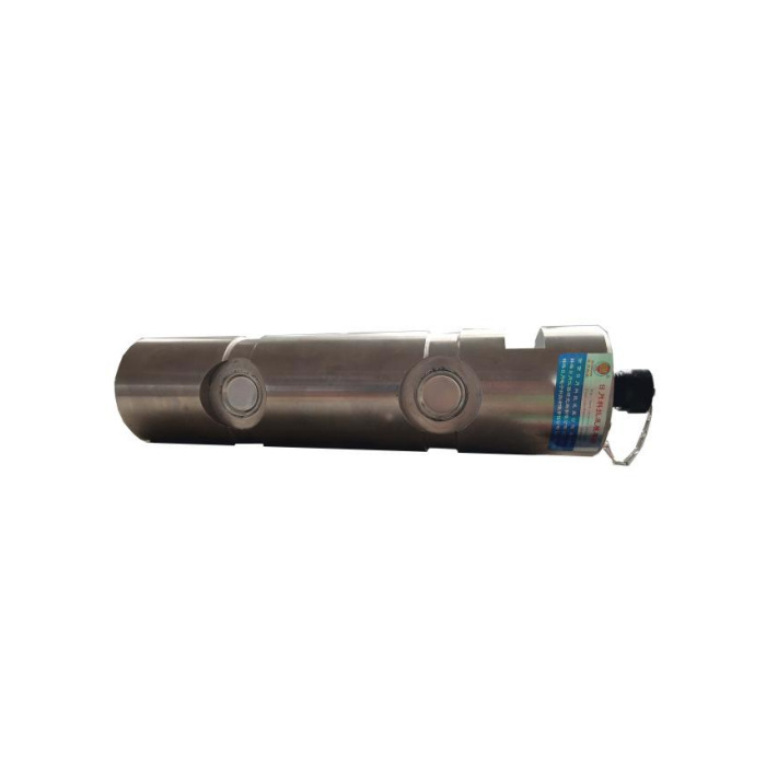

METRAVON MV-LC0012 is a load pin with three nominal diameter-60 bearing lands and a technical range up to 20 t. It is a candidate for an instrumented joint only when the mating bores and support positions match its rated arrangement. In an old machine, a new sensing pin does not repair an oval bore, a loose bush or a misaligned bracket. Include those conditions in the replacement assessment before requesting the pin.
Inspect the bores before choosing a 60 mm load pin
Measure the joint in its safe unloaded condition and document the bushes, member widths, alignment and wear. The three diameter-60 lands carry negative tolerances of -0.03 and -0.08 mm in the reference. Use the approved fit for the actual application, not an arbitrary clearance based on the rounded diameter. Local edge contact or movement in a worn bush can change load introduction and repeatability. Decide whether bush or bracket repair is needed before defining the replacement sensor.
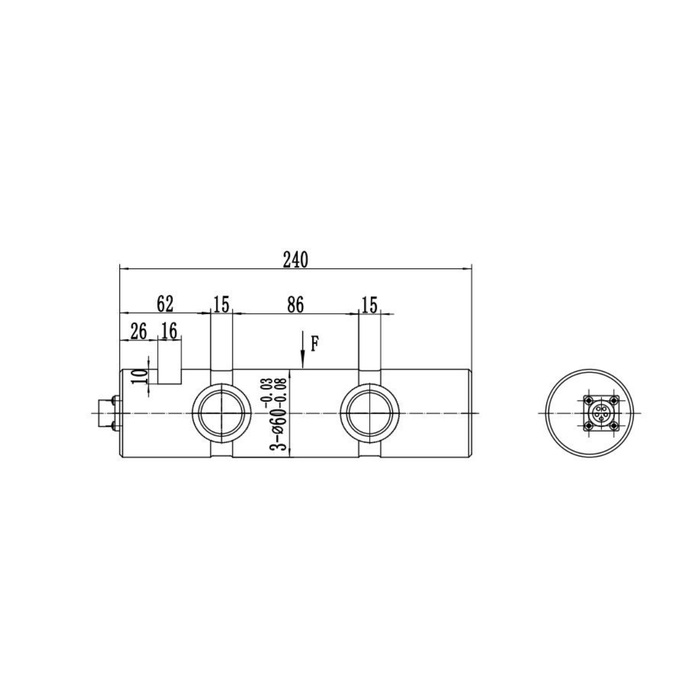
Carry the 240 mm outline into the installation drawing
The longitudinal reference is 240 mm. The dimension chain also includes a 62 mm end-to-section reference, an 86 mm central reference and two 15 mm relieved sections. A retaining notch is shown near one end and an electrical connector at the end face. These local dimensions identify different features; do not combine them into an assumed universal bearing span. Show which members contact each land, how axial movement is stopped and how the notch relates to the required measurement direction.
| Item | Value | Selection notes |
|---|---|---|
| Technical maximum reference | 20 t | Use joint reaction rather than machine payload alone. |
| Bearing lands | Three 60 mm diameters | Negative tolerances require a specified mating-bore fit. |
| Longitudinal / central references | 240 / 86 mm | Check the distinct datums on the controlled drawing. |
| Relieved-section widths | Two 15 mm references | Do not place a supporting bush by eye from the photograph. |
| Bridge sensitivity | 1.0 +/-0.015 mV/V | Verify excitation and usable input range on the existing reader. |
| Current-output alternative | 4-20 mA / 24 V DC | Order the actual amplified build, not merely a new cable. |
Retain the instrument only after checking its input
A bridge reader must suit the 1.0 +/-0.015 mV/V reference and 10-12 V DC excitation. If the existing controller accepts a process signal instead, specify the appropriate 4-20 mA build or external conditioning with its supply and scaling. The reference current option uses 24 V DC; it is not permission to power the bridge at that voltage. CANopen options require a matching configuration and integration record. The connector drawing distinguishes front and rear views, so terminal functions must be checked from the correct side.
Separate re-zeroing from a mechanical correction
After fitting the pin, inspect the unloaded reading before and after securing the retention. If moving the keeper, tightening the assembly or changing the mechanism position changes the reading unexpectedly, investigate contact or restraint before adjusting the display. Compare reference loads through the same final joint and record unloading return. The specification gives 0.5% FS precision and 0.5% FS per 10 deg C temperature effect; a zero adjustment at one temperature does not validate performance across the operating conditions.
Define the replacement package rather than only the pin
State whether the offer should include a mating cable, reader or conditioning equipment and installation drawing. Select alloy steel or stainless steel against actual water and corrosion exposure, and confirm the completed connector arrangement for IP67. The operating-temperature entry is -40 to +85 deg C. Keep the sensor 200% FS safe-load reference separate from the allowed load of the machine. Neither that figure nor a CANopen Safety option establishes approval for a lifting protective system.
For a different nominal land size and extended layout, compare the MV-LC0014 dimension discussion. Its 63 mm reference, length and rating differ; it is not established as a drop-in replacement for the 60 mm arrangement.
Bore repair, retained instruments and keeper adjustment
Q1. Will a new pin correct a loose joint?
Not by itself. Inspect the bore and bush condition, member alignment and permitted contact areas. Define any required mechanical repair before accepting the replacement pin arrangement.
Q2. Can the existing bridge indicator be kept?
Check its excitation, sensitivity range, connection functions and calibration method against the supplied pin. Retention of the instrument does not remove the need to verify the complete assembly under reference loads.
Q3. Should the keeper be tightened until the zero stops moving?
No installation torque is established by that symptom. Check the approved retention detail and whether tightening introduces unintended restraint. Correct the contact or assembly problem before attempting calibration.
