


 Chinese
 Spanish
 Russian
 Portuguese
 French
 German
 Indonesian
 Thai
 Vietnamese
 Arabic
 Italian
 Turkish
 Polish
 Japanese


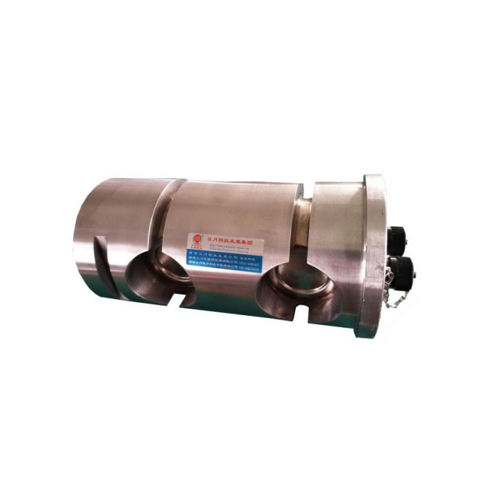

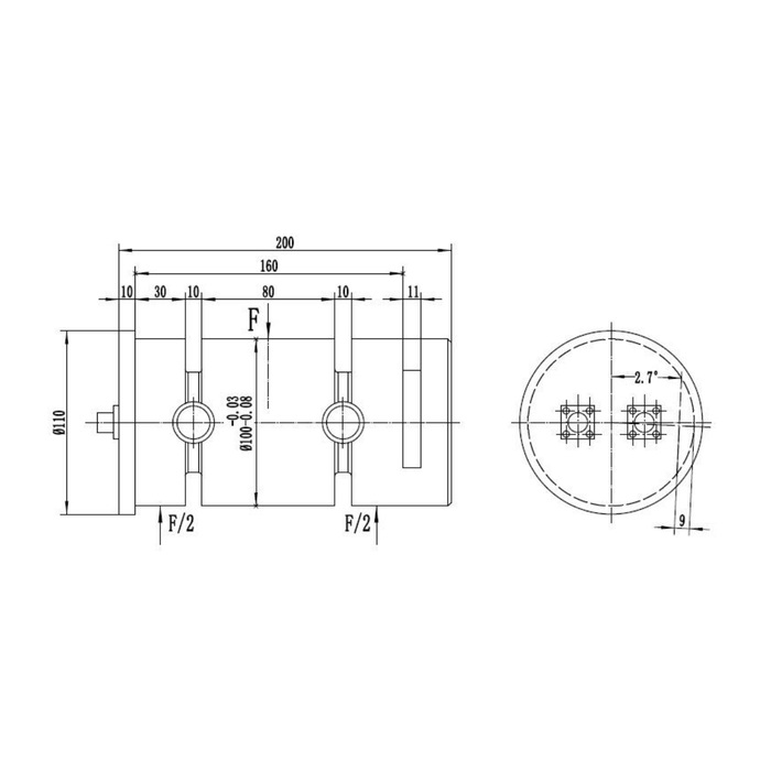
METRAVON MV-LC0011 is a load pin for measuring the reaction transmitted through a mechanical joint. Its technical load reference reaches 25 t. The outline shows a central F load and two F/2 reactions, so the supporting arrangement is part of the measurement definition. For a sheave, hoist linkage or other instrumented connection, provide a section through the joint rather than selecting a pin from machine payload alone.
Check the load pin against the two-support joint
The reference outline has a 200 mm longitudinal dimension, a 160 mm secondary reference, a diameter-100 bearing region and a diameter-110 end feature. The diameter-100 callout includes negative size tolerances. It is not a recommendation to make an unrestricted 100 mm bore. Identify the loaded member, both outer members, bushes, contact widths and gaps on the assembly section. Those positions must agree with the rated pin drawing; the overall length is not a substitute for the distance between support reactions.
| Item | Value | Selection notes |
|---|---|---|
| Technical load reference | Up to 25 t | Confirm the offered rating for the supplied support geometry. |
| Longitudinal references | 200 / 160 mm | Keep the complete datum chain on the joint section. |
| Bearing / end-feature diameters | 100 / 110 mm | Use toleranced dimensions and approved contact faces. |
| Drawing load arrangement | F with two F/2 reactions | Show the actual central and outer member widths. |
| Bridge / current supply entries | 10-12 / 24 V DC | These belong to different electrical configurations. |
| Precision / temperature entry | 0.5% FS / 0.5% FS per 10 deg C | Do not interpret these as percent of the instantaneous load. |
Retain the measurement direction without trapping the connection end
The force arrow and the two local sensing sections establish an oriented measurement. The retaining arrangement must prevent unwanted rotation and axial migration while preserving the intended bearing contacts. The reference photograph shows two connector positions at an end. Reserve the space needed to mate, protect and disconnect the actual delivered connectors. Do not use a plug, cable or connector housing to restrain rotation, and do not derive the number or independence of measuring channels from the photograph alone.
Specify the electrical option before ordering the reader
The electrical entries describe alternative bridge, current and CAN routes. The bridge reference is 1.0 +/-0.015 mV/V with 10-12 V DC excitation; the 4-20 mA entry names 24 V DC. CANopen and CANopen Safety are option references, not proof that every pin includes a bus interface or an approved protective function. State the selected output, controller input and required channels in the enquiry. Obtain the delivered connector identity, mating-face view and terminal schedule before energising a replacement.
Agree what the indicated load represents
A joint reaction is not automatically the same value as rope tension, hook load or carried mass. Record the mechanism positions and force directions that determine that relationship. Reference precision is 0.5% FS, with a separate temperature-effect entry of 0.5% FS per 10 deg C. Assess the required working-load resolution on that full-scale basis. A larger pin selected only for overload margin may not resolve the small load changes needed by the monitoring process.
Record a joint-level acceptance result
Compare independent reference loads with the final indication at the required mechanism positions. Include repeated loading and return to the unloaded condition, and retain the bush, spacer, orientation and controller records. Check actual exposure against IP67 and the -40 to +85 deg C operating interval. The 200% FS safe-load figure belongs to the sensor reference, not to an approved proof test of the hoist or surrounding structure. Safety-related use requires the exact option documents and assessment of the whole installed function.
Support changes, channel evidence and replacement readings
Q1. Can one support be moved to suit a narrower bracket?
Only with an approved rated arrangement. The illustrated reaction positions are part of how force enters the sensing sections. A narrower bracket or different bush width changes that arrangement even when the pin still passes through the bore.
Q2. Do the two visible connectors establish two independent safety channels?
No channel architecture is established by appearance. Ask for the supplied channel definitions, connector assignments and option documentation. A protective function also depends on the controller and the rest of the equipment.
Q3. Why can a correctly sized replacement still read differently?
Compare support spacing, contact widths, pin orientation and the old calibration condition before changing the reader span. A mechanically different load introduction can change the response; matching nominal diameter and sensitivity does not settle that question.
