


 Chinese
 Spanish
 Russian
 Portuguese
 French
 German
 Indonesian
 Thai
 Vietnamese
 Arabic
 Italian
 Turkish
 Polish
 Japanese


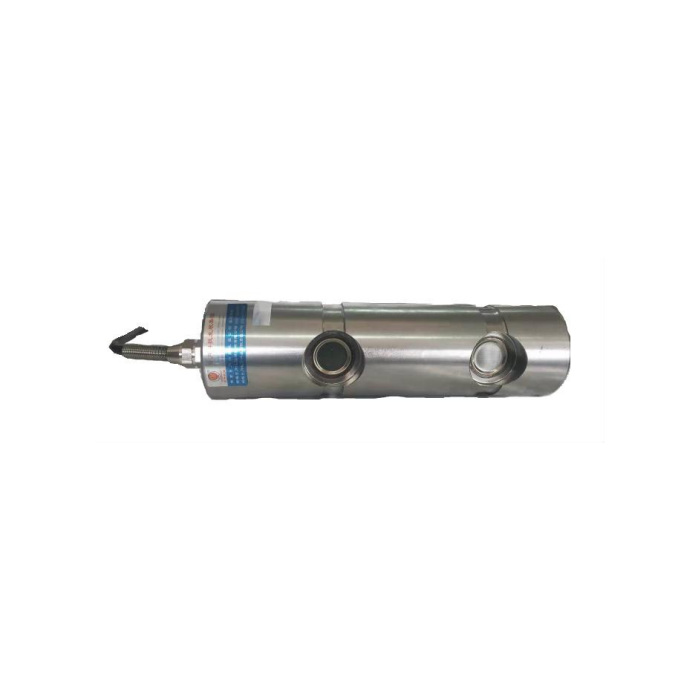

METRAVON MV-LC0010 is a load pin with a diameter-55 reference, a 200 mm longitudinal outline and a technical maximum of 15 t. For an existing joint, those dimensions are only the start of the replacement check. The contact locations, retaining notch, force orientation and controller interface must also match the approved supplied version. A pin that enters the old bore is not yet a verified replacement.
Document the old joint before removing the sensing pin
Keep the old mechanical drawing, fitted direction, bush and spacer positions, connection record and instrument settings with the replacement enquiry. Inspect the bore and contact surfaces during a safely supported shutdown. The actual pin reaction needs to be established from the mechanism, rather than assumed equal to a lifted or carried mass. If the old failure involved wear, impact or changing zero, record those conditions so that replacement does not leave the original mechanical cause in service.
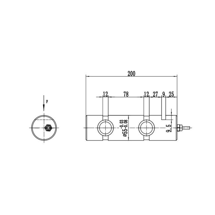
Compare the 55 mm load pin contacts and retaining detail
The outline shows a 200 mm longitudinal reference, two 12 mm relieved sections and a 78 mm central reference. The diameter-55 lands carry negative tolerances of -0.03 and -0.08 mm. An end notch is shown with separate local dimensions. Map the old loaded member, both supports and axial retention onto those datums. Do not move a keeper or bush simply to use an old fastener location if that changes contact with the sensing regions or blocks the cable outlet.
| Item | Value | Selection notes |
|---|---|---|
| Technical maximum reference | 15 t | Select against the actual joint reaction and operating conditions. |
| Bearing-land diameter | 55 mm | Use the controlled negative tolerances and mating fit. |
| Longitudinal / central references | 200 / 78 mm | Compare all contact locations, not just the old overall length. |
| Relieved sections | Two 12 mm references | Check bush and loaded-member edges against the rated section. |
| Bridge supply / current-option supply | 10-12 / 24 V DC | The output build determines which supply applies. |
| Connection check | Delivered terminal functions | Reconcile the reference colour-list and polarity conflict. |
Release the output version before restoring power
For the bridge configuration, the reference is 1.0 +/-0.015 mV/V with 10-12 V DC excitation. A separately listed 4-20 mA route uses a 24 V DC reference, and CANopen options require their own controller and cable documentation. Check the actual offered channel before reusing a connection. The reference bridge colour list and circuit disagree on signal polarity, so colour matching is not an adequate wiring method. Require delivered terminal functions and verify the loaded response under controlled conditions.
Re-establish scaling through the installed force path
Compare independent agreed reactions with the indication after the pin, keeper, bushes and cable are in their final positions. Record repeated loads, unloading return and any important mechanism positions. The 0.5% FS precision entry and separate 0.5% FS per 10 deg C temperature effect must be considered at the useful working loads. Reusing the old display span without a loading check can conceal a changed mechanical arrangement or output scale. Agree how the reaction is converted if the display reports another quantity.
Keep replacement approval separate from safety approval
Specify material, the completed IP67 cable arrangement and the actual pin temperature against the -40 to +85 deg C operating interval. Do not use the sensor 200% FS safe-load entry as a machine test target. If the pin participates in protective monitoring, require the selected channel architecture, controller behaviour and system validation records. The CANopen Safety option reference does not by itself approve the complete protective function or establish a certified safety level.
The MV-LC0008 short-joint arrangement has a 98 mm reference rather than this 200 mm outline. Use that comparison to identify a different installation requirement, not to establish a direct substitute.
Replacement identity and the final loaded check
Q1. Is a nominal 55 mm diameter enough to approve the replacement?
It does not settle length, tolerances, contact positions, restraint or output. Compare the complete old and proposed installation drawings and verify the final reaction measurement.
Q2. Can MV-LC0008 be substituted because its body is also 55 mm?
Its outline is shorter and its technical maximum differs. A common rounded diameter does not approve the same support arrangement or load. Review both rated drawings before considering either product.
Q3. Why is a loading check necessary if the display shows zero?
Zero only checks one condition. The installed sensitivity, polarity, scaling and repeat response still need comparison with a known applied reaction. A plausible unloaded value cannot confirm a correct loaded indication.
