


 Chinese
 Spanish
 Russian
 Portuguese
 French
 German
 Indonesian
 Thai
 Vietnamese
 Arabic
 Italian
 Turkish
 Polish
 Japanese


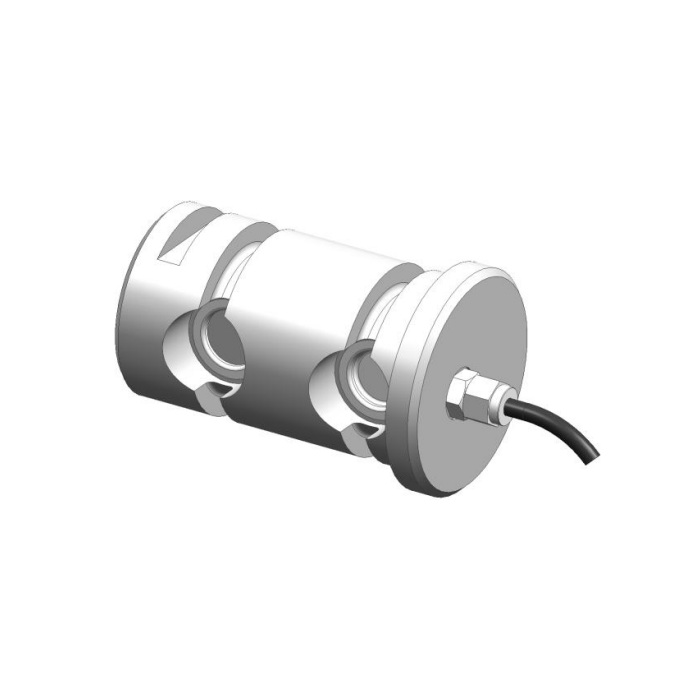

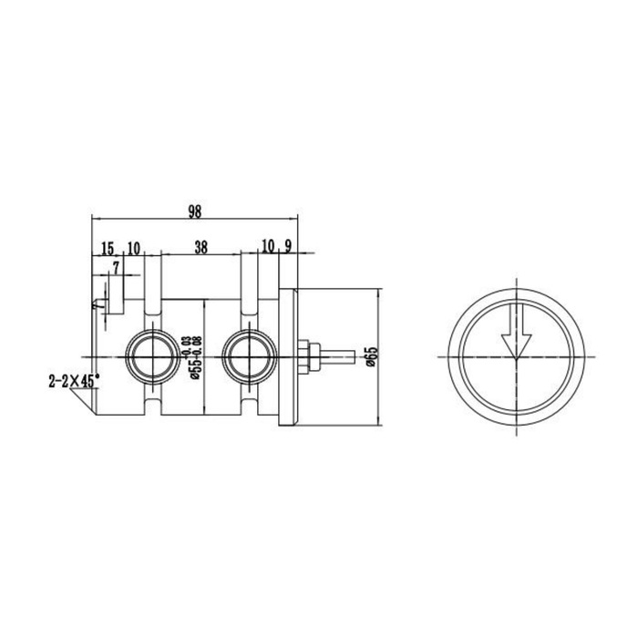
METRAVON MV-LC0008 is a short load pin with a 98 mm longitudinal outline and a technical maximum reference of 5 t. Its end view carries a direction arrow, while the body has a diameter-55 reference and a diameter-65 end feature. Selection must resolve the force direction and supporting contacts, not merely whether a 55 mm pin enters the bore. The end cable also needs space beyond the body dimension.
Fix the measurement direction before routing the cable
Relate the end-view arrow to the reaction in the real joint and specify how that orientation is retained. A cable route convenient for the installer does not define the sensing direction. Show both the restrained pin and the moving members through the operating positions that matter. If the existing keeper places the arrow incorrectly, obtain a reviewed installation arrangement rather than rotating the cable gland or modifying the pin. Any alternative body or connection arrangement needs confirmation before order.
Check where the short load pin is actually supported
The 98 mm outline includes local end features and two 10 mm relieved sections around a 38 mm central reference. The diameter-55 callout has negative tolerances, and the diameter-65 end is a separate feature. Use the released contact and fit information with a section of the bracket and bushes. Length left over beside a bush is not automatically additional rated bearing surface. In a short assembly, a small shift of a spacer or support can move contact towards a relieved section.
| Item | Value | Selection notes |
|---|---|---|
| Technical maximum reference | 5 t | Confirm rated reaction and the approved measurement direction. |
| Body outline length | 98 mm | Allow additional room for the gland and cable. |
| Body / end-feature diameters | 55 / 65 mm | Use the supplied tolerances and contact-face definitions. |
| Central / relieved references | 38 / 10 mm | Two relieved sections require a complete support-section check. |
| Electrical choices | Bridge, current or CAN option | Specify one documented build with supply and cable functions. |
| Direction indication | Arrow in end view | Relate it to the joint reaction and approved retention. |
Match the selected output to the receiving hardware
The bridge entry is 1.0 +/-0.015 mV/V at 10-12 V DC. The option list also includes 4-20 mA with a 24 V DC reference, CANopen and CANopen Safety. Identify the supplied version and its cable functions before retaining the old controller or applying power. These alternatives do not establish simultaneous outputs or a certified redundant channel arrangement. For a safety-related monitoring requirement, obtain the actual option documentation and validate the entire installed function separately.
Use a repeatable acceptance load through the final supports
Record pin orientation, bush positions, retention and reader settings before testing. Compare agreed reference reactions, repeated loading and the return after unloading. Review the useful load changes against 0.5% FS precision and the separate 0.5% FS per 10 deg C temperature-effect entry. The indicated value must represent the intended joint reaction or a documented conversion to another quantity. Replacing a pin does not automatically preserve an old payload or rope-tension calibration.
Keep environmental and mechanical limits separate
For the selected material, check water, cleaning and corrosion at the end cable and its termination. IP67 and -40 to +85 deg C are product references, not ratings for an unspecified connector assembly or machine. The safe-load entry is 200% FS; it is not an allowable working overload or permission to proof-test the assembled bracket. Define the surrounding mechanical load limit and any protective monitoring requirements independently from the pin order.
Compare the MV-LC0010 replacement checks when a 200 mm outline is relevant. A common 55 mm diameter does not remove the need to review different rated loads, support geometry and electrical builds.
Orientation changes, shared diameters and power supplies
Q1. Can the pin be turned to make its cable point downwards?
Only if the resulting position preserves the approved measurement orientation. First establish the arrow-to-load relationship and keeper position; solve cable access within that arrangement.
Q2. Is this a shorter version of the diameter-55 MV-LC0010?
A shared nominal diameter does not make the pins mechanically interchangeable. Their outline lengths, local contact dimensions and technical maximum references differ. Compare both rated drawings and the actual joint section.
Q3. Does an existing 24 V supply establish electrical compatibility?
Not by itself. The bridge entry uses 10-12 V DC excitation, whereas the 4-20 mA alternative references 24 V DC. Confirm the delivered interface and terminal functions before connecting that supply.
