


 Chinese
 Spanish
 Russian
 Portuguese
 French
 German
 Indonesian
 Thai
 Vietnamese
 Arabic
 Italian
 Turkish
 Polish
 Japanese


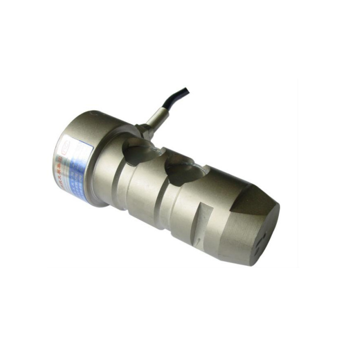

METRAVON MV-LC0007 is a compact load pin with a bridge output and a technical range up to 3 t. The drawing shows a 114 +/-0.1 mm longitudinal reference and a cable connection that projects radially from the end region. It may suit a constrained joint only after bearing contacts, orientation and cable space are checked together. A short body does not establish that the complete connection will clear a nearby frame or guard.
Allow for more than the compact load pin body
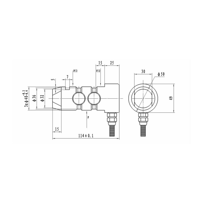
The outline identifies three nominal diameter-40 regions, a diameter-50 end feature and a 114 +/-0.1 mm length reference. The cable entry projects below the body in the illustrated view. Include the gland, cable departure, movement and service access in the available-space check. Use the delivered tolerances and controlled datums when assessing the fit. Do not force the cable against a bracket to make the nominal body length fit, or rotate the pin solely to recover cable clearance.
Check the illustrated reaction arrangement before making a keeper
Two F/2 reactions are shown above the pin and F below its central region. The actual loaded and supporting members must introduce force in the approved locations and direction. The notch and end details require a defined retention arrangement; their appearance is not a torque or clamp instruction. Show the mating members, bushes, gaps and axial stops in section. A keeper that changes the contact condition can affect the measurement even if the pin is securely held.
Provide a bridge acquisition path, not just a PLC process input
The documented channel is 1.0 +/-0.015 mV/V with 10-12 V DC excitation. It requires an appropriate weighing input or bridge conditioner capable of supplying excitation and reading the differential signal. The parameter table does not establish a direct 4-20 mA or CAN version for this model. If the control system needs such a signal, define an external conversion arrangement or obtain explicit product-specific option documentation; do not transfer another model electrical list into this selection.
| Item | Value | Selection notes |
|---|---|---|
| Technical load reference | Up to 3 t | Agree the pin reaction and its approved contact arrangement. |
| Longitudinal reference | 114 +/-0.1 mm | This is not the complete radial cable-clearance envelope. |
| Body / end-feature references | 40 / 50 mm diameters | Check controlled tolerances and mating geometry. |
| Bridge sensitivity | 1.0 +/-0.015 mV/V | Requires excitation and a suitable low-level signal input. |
| Excitation | 10-12 V DC | Do not apply an assumed process-transmitter supply. |
| Documented output boundary | Bridge output | Direct current or bus operation needs separate evidence. |
Check the assembled response at the required low loads
Specify the useful reaction interval as well as the maximum, and agree a loading reference suitable for that interval. Precision is listed as 0.5% FS and temperature effect as 0.5% FS per 10 deg C. These entries should be considered alongside acquisition performance and temperatures at the pin. Repeat loaded measurements and check the unloaded return after securing the keeper and routing the cable. Correct an assembly-related zero change before relying on a new span adjustment.
Define exposure and maintenance access before ordering
Choose alloy steel or stainless steel for the actual joint environment and verify the IP67 arrangement with the cable entry and termination completed. The operating-temperature range is -40 to +85 deg C, not an assurance that the whole machine shares those limits. Include a safe way to support the joint during pin removal. The sensor 200% FS safe-load figure cannot be used to approve lifting hardware or to set an equipment proof-load procedure.
PLC inputs, clearance and keeper effects
Q1. Can this connect directly to a 4-20 mA PLC input?
The documented output is a millivolt-per-volt bridge, not a current loop. Use a suitable bridge input or a specified external conditioner and confirm excitation, scaling and calibration for the assembled system.
Q2. Does the 114 mm length settle whether the pin fits?
No. The radial cable entry, mating fit, support contacts and retaining parts also need space. Compare the complete installed envelope and removal path with the actual bracket.
Q3. Can the retaining notch be used to clamp away a changing zero?
Do not use clamping as an improvised calibration correction. Check the intended keeper contact and whether it adds restraint or changes bearing load. Resolve that mechanical cause before adjusting the reader.
