


 Chinese
 Spanish
 Russian
 Portuguese
 French
 German
 Indonesian
 Thai
 Vietnamese
 Arabic
 Italian
 Turkish
 Polish
 Japanese



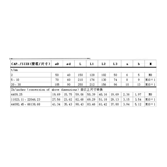
METRAVON MV-LC0006 is a load pin offered within a 2-30 t nominal range, with different outlines for different capacities. Selecting a higher rating can change the pin diameter, overall length, loaded region and retention detail. For an instrumented linkage or sheave joint, identify the required pin reaction and the available assembly space together. A capacity change is not automatically a sensor-only replacement.
Select the load pin capacity and dimensional row together
The 2 t row gives a 40 mm main diameter and 150 mm L dimension. At 5 and 10 t, those entries become 60 and 210 mm; at 20 and 30 t, they are 90 and 250 mm. The end diameter D also changes from 50 to 70 to 105 mm. These are metric drawing entries, not one interchangeable family envelope. Select and manufacture from approved metric drawings; do not use the imperial conversion values shown in the reference gallery table. Ask for the rated drawing before altering the bracket or ordering bushes, including fit tolerances and the permitted contact positions for the selected load.
| Item | Value | Selection notes |
|---|---|---|
| 2 t: D / d / L | 50 / 40 / 150 mm | L1=128, L2=102, L3=50 mm; M8 drawing entry. |
| 5 or 10 t: D / d / L | 70 / 60 / 210 mm | L1=176, L2=130, L3=74 mm; M10 x 1 entry. |
| 20 or 30 t: D / d / L | 105 / 90 / 250 mm | L1=212, L2=156, L3=96 mm; M10 x 1 entry. |
| Bridge channel | 1.0 +/-0.015 mV/V | Match a bridge reader and its excitation, not a bare process input. |
| Amplified alternative | 4-20 mA / 24 V DC | Confirm the supplied version and actual terminal functions. |
| Nominal family range | 2-30 t | Do not interpolate an unlisted rated outline without confirmation. |
Distinguish the loaded region from the total insertion length
The drawing labels L, L1, L2 and L3 separately. L3 is 50 mm for 2 t, 74 mm for 5/10 t and 96 mm for 20/30 t. The longer L dimension cannot replace that central-region check. Draw the central member and the two supporting members on the same section, showing bush widths, gaps, axial restraint and cable exit. Do not assign every visible cylindrical surface a bearing role. Confirm how the direction of the measured reaction is maintained when the surrounding mechanism moves.
Choose the interface before calculating the installation package
A bridge version requires an input suited to 1.0 +/-0.015 mV/V and 10-12 V DC excitation. A 4-20 mA configuration is separately referenced at 24 V DC; CANopen and CANopen Safety are further option references. Specify which output the receiving instrument needs, with cable length and any external conditioner. The list does not mean that all outputs are present on one pin. Channel independence and any safety-related application require actual configuration documents rather than inference from the option names.
Compare the useful reaction with full-scale performance
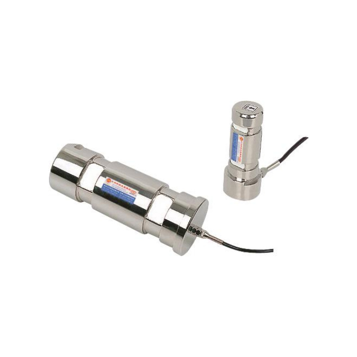
The maximum joint reaction can differ from rope tension or the carried load because of mechanism geometry. Provide the force directions and operating positions that establish that relationship. The 0.5% FS precision entry is based on the selected full scale, and temperature effect is separately listed as 0.5% FS per 10 deg C. Check the smallest change that matters to the process against those entries and the reader. Increasing capacity should follow a load assessment, not replace it.
Include mechanical work and acceptance in the quotation scope
State whether a replacement requires bushes, retaining parts, a mating connection or a different reader, and distinguish those items from the pin itself. Agree reference loading through the completed joint and compare repeat response and unloading return. Assess IP67 and the -40 to +85 deg C operating interval at the actual location, with the selected material and cable termination. The 200% FS safe-load entry is not an approved overload-test instruction for the machine, bracket or surrounding lifting equipment.
Capacity upgrades and the replacement package
Q1. Can a 2 t pin be upgraded to 10 t in the same bracket?
The listed main diameter changes from 40 to 60 mm and L from 150 to 210 mm. The joint therefore needs a dimensional and structural review, not merely an instrument range change. The higher sensor rating does not raise the bracket rating.
Q2. Are 5 t and 10 t versions necessarily electrically identical?
Their displayed mechanical row is shared, but the offered electrical build and calibration must still be specified. Confirm output, excitation, terminal functions and rated scaling for the supplied item.
Q3. What should be sent for a firm replacement offer?
Send the selected capacity, joint section, existing pin drawing, contact widths and retention detail. Add the required interface and identify whether any bushes, cables or conditioning equipment belong in the quoted package.
