


 Chinese
 Spanish
 Russian
 Portuguese
 French
 German
 Indonesian
 Thai
 Vietnamese
 Arabic
 Italian
 Turkish
 Polish
 Japanese



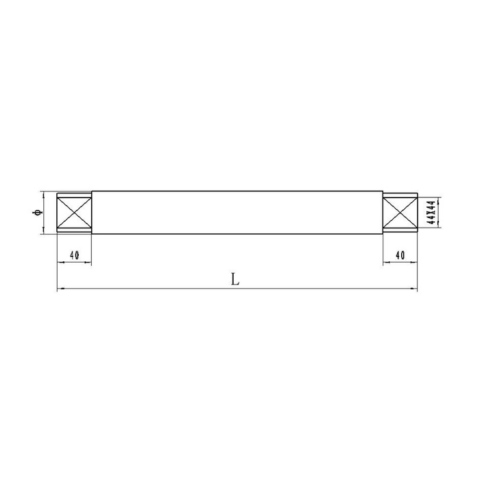
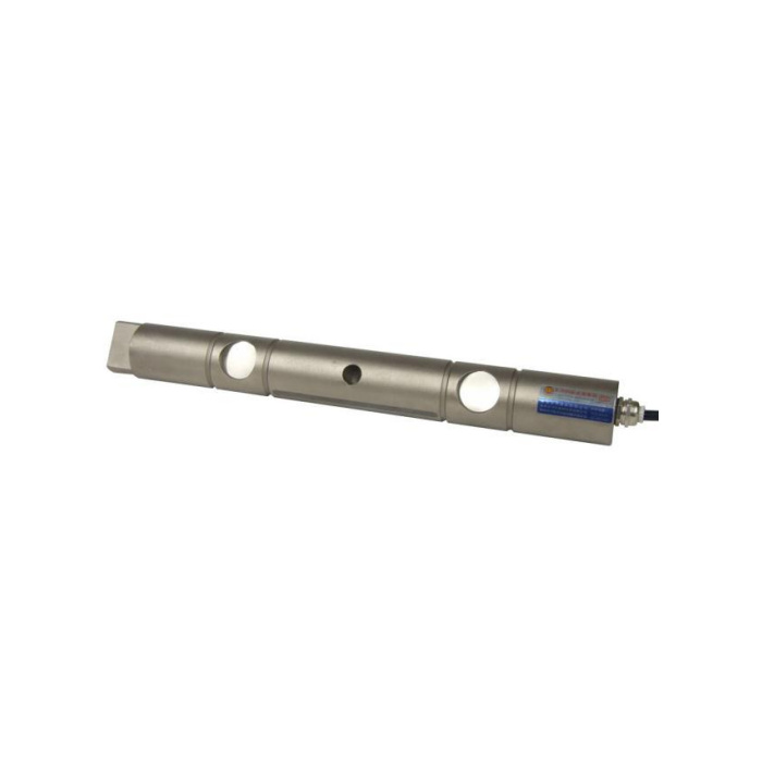
METRAVON MV-LC0005 is a bridge-output load pin for measuring force in an instrumented joint, with a technical maximum reference of 5 t. Its general outline labels the overall length as L and includes an unnumbered diameter symbol. Those labels are not release dimensions. A project enquiry should establish the required length, mating geometry and load contacts through an approved rated drawing, rather than estimating a pin from the photograph.
Confirm the load pin dimensions that the general outline leaves open
The illustration carries 40 mm end references and a 44 x 44 callout, but it does not assign numerical values to overall L or the marked diameter. Identify exactly which end and contact features apply to the offered configuration. Send the existing pin or joint drawing with the available insertion and removal space. Do not manufacture bushes, drill a bracket or promise an old-pin replacement from an unscaled image. A project-specific dimensional review does not itself establish that every requested size can be supplied.
| Item | Value | Selection notes |
|---|---|---|
| Technical maximum reference | 5 t | Require the rated joint arrangement and measurement direction. |
| Overall length label | L; no fixed value shown | Obtain the approved numerical dimension for the offered pin. |
| Diameter label | Unnumbered diameter symbol | Do not choose the bore size from the photograph. |
| End-detail references | 40 mm; 44 x 44 callout | Confirm their function and applicability on the rated drawing. |
| Bridge output / excitation | 1.0 +/-0.015 mV/V / 10-12 V DC | Specify a suitable bridge input or external conditioner. |
| Precision / temperature effect | 0.5% FS / 0.5% FS per 10 deg C | Check the useful reaction interval and actual temperatures. |
Define the joint reaction and the supporting contacts
Show the loaded member, supports, bushes, gaps and axial retention in section, with the direction and largest value of the pin reaction. That reaction is the quantity transmitted through the joint; it must not be labelled as rope tension or payload without the relevant mechanism relationship. Record any moving positions or contact changes that affect the intended measurement. The 5 t reference cannot be transferred to an arbitrary support span or to a bearing arrangement that has not been reviewed.
Provide a genuine bridge-reading channel
The documented electrical output is 1.0 +/-0.015 mV/V with 10-12 V DC excitation. It needs a compatible weighing input or a defined bridge conditioner, not a direct process-current input. Do not assume current, CAN or redundant channels from other load pins in the catalogue. Obtain the delivered cable and terminal functions before connection, since the reference colour legend and circuit disagree on signal polarity. The receiving display or PLC scaling must be verified against applied reaction rather than inferred from the connector appearance.
Assess useful force changes and the final retained state
The reference precision is 0.5% FS, with temperature effect listed separately as 0.5% FS per 10 deg C. Compare the useful force interval and actual pin temperature with that full-scale basis. Use agreed reference reactions after the supports, retention and cable restraint are in their final positions. Compare repeated response and return after unloading; include the mechanism positions relevant to the measurement. A display that can be zeroed is not evidence that the joint force path and loaded sensitivity are correct.
Keep the pin specification separate from equipment approval
Review the selected alloy steel or stainless steel and IP67 arrangement against corrosion, water and cleaning at the installed joint. The operating-temperature reference is -40 to +85 deg C. Do not use the sensor 200% FS safe-load entry as an instruction to overload the complete machine, keeper or bracket. Any protective or lifting-related use also needs the documented system requirements and validation. This bridge-output product description does not establish an approved safety function or direct interchangeability with an old pin.
Unspecified dimensions, supplied geometry and end contacts
Q1. Can the pin length be taken from the L label?
L is a dimensional variable in the general outline, not a numerical size. Obtain the offered rated drawing with actual length, diameter, contacts and retention before ordering or machining the surrounding joint.
Q2. Does the reference mean any custom diameter or length is available?
No unrestricted custom capability is established. Submit the joint dimensions and reaction for review, then obtain a confirmed mechanical configuration and quotation.
Q3. Can the 40 mm end details be treated as approved support widths?
Their exact function and allowed contact need to be defined on the supplied drawing. Do not equate a local length callout with a rated bearing contact without checking the complete force path.
