


 Chinese
 Spanish
 Russian
 Portuguese
 French
 German
 Indonesian
 Thai
 Vietnamese
 Arabic
 Italian
 Turkish
 Polish
 Japanese


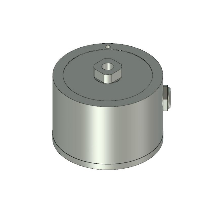

METRAVON MV-LC0004 is a spoke-type force load cell with a threaded connection reference and five rated choices from 111 to 2224 N. It can be assessed for a force-test assembly where the adaptor, load direction and acquisition channel are defined together. The thread is not a complete fixture design. Confirm how force is introduced and reacted, and provide protection appropriate to the listed IP50 configuration.
Release the threaded force-test adaptor before making hardware
The outline labels 1/4-28 UNF-2B with a 9.4 mm depth reference. This is not a metric thread, and the quoted depth is not an automatic engagement or tightening-torque instruction. Obtain the approved connection for the intended force direction, including mating thread, engagement, contact and locking requirements. Show whether the fixture experiences compression, tension, reversal or an offset load. A threaded connection and a general force-testing description do not establish an approved lifting attachment or a complete suspended-load assembly.
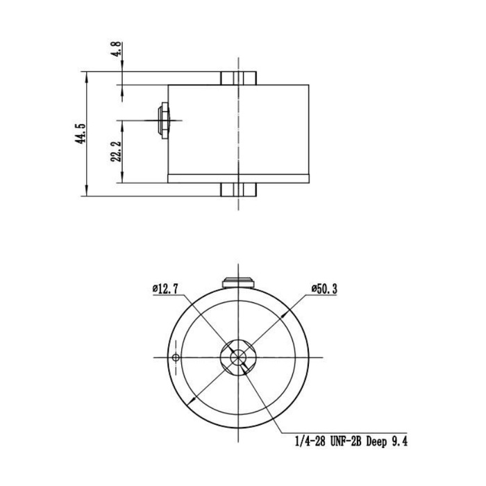
Check the envelope beyond the round body
The drawing identifies a 50.3 mm outside diameter, a 44.5 mm overall vertical reference and a 12.7 mm centre feature. The centre protrusion and side electrical connection must be included when checking access and stack height. Do not scale the picture to establish thread or connector dimensions that are not specified. Provide space to assemble and remove the actual adaptor without transmitting unintended torque through the sensing body or preventing access to the electrical connection.
Select the spoke-type force load cell with the correct signal scale
The 111, 222 and 1112 N versions are listed at 1.0 mV/V, while 445 and 2224 N use 2.0 mV/V. The bridge supply entry is 10-20 V DC, with 730 +/-5 ohms input and 700 +/-1 ohms output resistance. Check the receiving channel and its excitation before choosing the version. Direct 4-20 mA or RS485 operation is not established for this raw bridge. A process controller needs a defined bridge acquisition or conditioning arrangement, followed by calibration through the completed force chain.
| Item | Value | Selection notes |
|---|---|---|
| 111 / 222 / 1112 N versions | 1.0 mV/V | Specify rating and bridge sensitivity together. |
| 445 / 2224 N versions | 2.0 mV/V | Check input range before retaining an existing reader. |
| Thread / depth reference | 1/4-28 UNF-2B / 9.4 mm | Confirm the mating adaptor, engagement and load direction. |
| Diameter / overall vertical reference | 50.3 / 44.5 mm | Include the side connection and complete fixture stack. |
| Bridge supply | 10-20 V DC | Use the delivered connection schedule and excitation requirements. |
| Precision / protection | 0.3% FS / IP50 | Provide a suitable protected test installation. |
Specify enclosure protection instead of relying on general sealing claims
The model-specific technical table gives IP50 and 17-4 PH stainless steel. Do not infer a wet-process or washdown rating from broad water-resistant descriptions. State dust, fluid and cleaning exposure and define any protective enclosure without restricting the force path. The temperature-compensated interval is -10 to +65 deg C, while operation is listed at -40 to +85 deg C. Temperature effect is 0.05% FS per 10 deg C; requirements outside the compensated interval need explicit review rather than an assumed unchanged performance.
Verify the actual adaptor and load directions
Use agreed independent force references through the final fitted adaptor and reaction parts. Check repeat response, unloading return and each approved direction needed by the test. Reference precision is 0.3% FS, so compare it with the useful test increments and acquisition performance. Record the rated version and reader settings as part of the fixture record. The 150% FS safe-load reference is not permission to proof-load an unspecified threaded adaptor or to use the whole assembly as lifting equipment.
Adaptor identity, load reversal and wet test stations
Q1. Can an M6 adaptor be used because its diameter looks close?
No metric substitute is established by a similar nominal size. The reference specifies 1/4-28 UNF-2B. Use the approved mating thread and connection design for the intended force direction.
Q2. Does the threaded centre approve tension and compression reversal without further checks?
Define the required directions, adaptor and calibration before accepting that duty. The connection needs documented engagement and load introduction for the actual fixture; the thread label alone is insufficient.
Q3. Is a stainless body enough for a wet test station?
The listed protection is IP50. Provide the actual exposure and specify an appropriate enclosure or separately confirmed configuration. Material choice does not replace ingress-protection assessment.
