


 Chinese
 Spanish
 Russian
 Portuguese
 French
 German
 Indonesian
 Thai
 Vietnamese
 Arabic
 Italian
 Turkish
 Polish
 Japanese


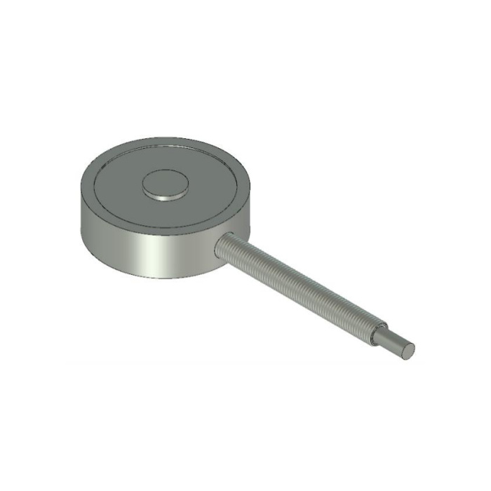

METRAVON MV-LC0003 is a low-profile button load cell for compression measurement in confined fixtures. The reference outline is 18.8 mm in diameter and 6.4 mm high, with six rated force choices from 111 to 4448 N. Capacity also determines the listed bridge sensitivity. A replacement decision therefore needs the rating, contact geometry and reader settings together, not just the available space beneath a loading platen.
Choose the button load cell rating with its bridge sensitivity
The 222 and 1112 N versions are listed at 1.0 mV/V. The 111, 445 and 2224 N versions use 2.0 mV/V, while 4448 N uses 2.5 mV/V. This is not one common output scale for the complete product family. State the preload, maximum compression and useful force changes before choosing capacity. Confirm the corresponding input range, excitation and calibration procedure on the retained reader. A higher-capacity replacement may change both mechanical operating conditions and the raw full-scale signal.
| Item | Value | Selection notes |
|---|---|---|
| 222 / 1112 N versions | 1.0 mV/V | Match the reader scale to the selected capacity. |
| 111 / 445 / 2224 N versions | 2.0 mV/V | Do not transfer the 1.0 mV/V setting across the family. |
| 4448 N version | 2.5 mV/V | Check that the acquisition input accepts the required signal. |
| Outside / button diameters | 18.8 / 5.1 mm | Keep the force contact on the approved button surface. |
| Full / body height references | 6.4 / 5.8 mm | Include the mating parts and radial cable in the installed envelope. |
| Precision / ingress protection | 0.25% FS / IP64 | Verify the complete fixture at its useful force interval. |
Load the raised button without bridging the sensing surface
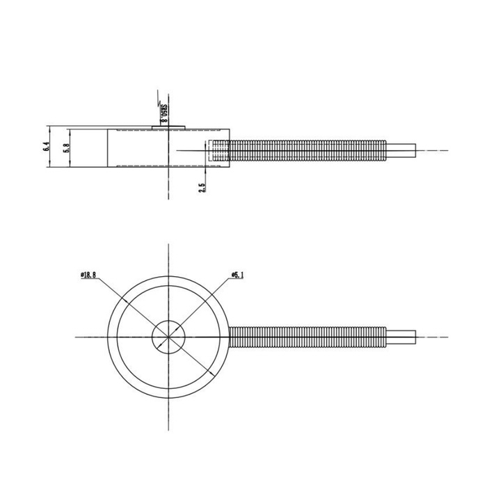
The dimensional reference has an 18.8 mm outside diameter, a 5.1 mm central button reference, 5.8 mm body height and 6.4 mm full height. The top curve is labelled SR50.8. Define the mating contact so that the intended force reaches the central button, with adequate base support beneath the sensor. A platen that also bears on the surrounding body can create a bypass path. The curved contact should not be interpreted as an unrestricted angular joint or an allowance for arbitrary side loading.
Include the cable in a low-height installation
A radial cable-protection feature extends from the body. Its space and strain relief must be included in the fixture layout even when the axial height is acceptable. Keep cable restraint from pulling the sensor out of its intended contact position. Confirm how the load cell is located and retained without imposing an unintended force on the measuring element. Do not add a clamp over the active top face simply because the thin body has no room for an existing mounting bracket.
Specify excitation and the environmental limit separately
Input resistance is listed as 730 +/-5 ohms and output resistance as 700 +/-1 ohms. The electrical supply entry is no more than 18 V DC; obtain the intended excitation rather than treating that maximum as a universal setting. The reference identifies 17-4 PH stainless steel and IP64. Choose a protected arrangement for the actual cleaning and fluid exposure instead of assuming that material or a sealed-looking photograph establishes immersion capability. The compensated temperature interval is -10 to +65 deg C, distinct from the -40 to +85 deg C operating interval.
Accept the low-profile fixture at its working forces
Use independent reference forces applied through the final loading button and base. Compare repeat readings and unloading return after all cable restraints and locating parts are fitted. The specified precision is 0.25% FS, with temperature effect of 0.05% FS per 10 deg C. Evaluate those full-scale entries against the required increments, not as percentages of each displayed load. The 150% FS safe-load entry is not a routine overload allowance for the fixture. No installation torque, lateral-force limit or tension rating is established by the button dimensions.
Where the project needs the larger N ratings of a taller miniature column, review the MV-LC0002 compact compression fixture checks. Reassess force range, contact and reader capability instead of selecting between the two by body diameter alone.
Reader changes, button contact and cleaning conditions
Q1. Can the same reader settings be used for 222 N and 445 N?
Their listed sensitivities differ: 1.0 and 2.0 mV/V respectively. Check the input capability and recalibrate for the selected rating and installed fixture instead of changing only the displayed capacity.
Q2. Why does the loading platen need to avoid the surrounding top surface?
The intended compression enters through the raised button. Contact with an unintended surrounding surface can bypass or alter that force path. Submit the platen and base sections for the approved contact arrangement.
Q3. Does 6.4 mm describe the complete installed stack?
It is the sensor height reference. The base, loading contact, locating parts and any required clearance add to the installed dimensions. The side cable also needs its own available space.
Q4. Can an IP64 stainless version be ordered for an unspecified washdown process?
Describe the cleaning pressure, fluids, temperature and exposure before accepting the sealing arrangement. Neither stainless steel nor the IP64 entry establishes suitability for every washdown or immersion condition.
