


 Chinese
 Spanish
 Russian
 Portuguese
 French
 German
 Indonesian
 Thai
 Vietnamese
 Arabic
 Italian
 Turkish
 Polish
 Japanese


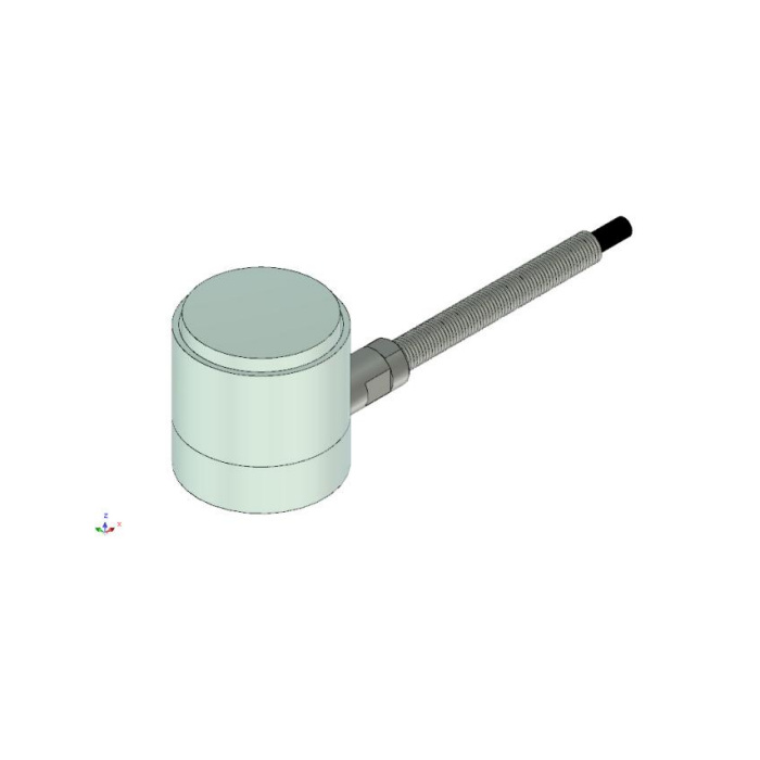

METRAVON MV-LC0002 combines a miniature compression outline with force ratings of 8896, 13344 or 22240 N. Its small diameter is an installation dimension, not evidence that a thin or uneven supporting plate is adequate. In a compact test fixture or machine force path, define the upper contact, lower support and cable exit before choosing the sensor. The approved compression arrangement determines whether the small body can measure the intended force without unintended restraint.
Build the fixture around the miniature compression load cell
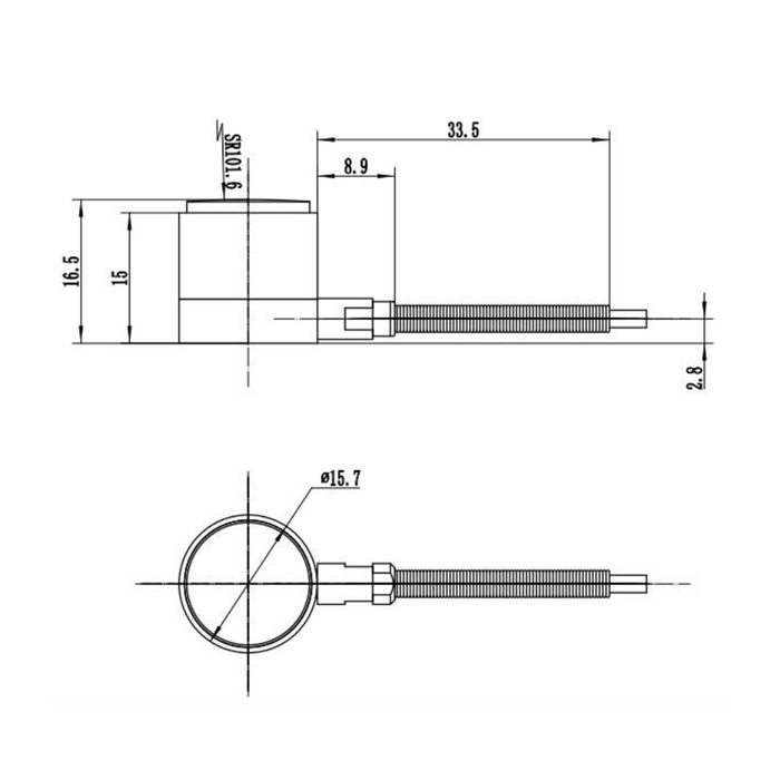
The outline gives a 15.7 mm diameter, a 16.5 mm overall height reference and a 15 mm body-height reference. The top surface carries an SR101.6 curvature callout. Use the corresponding approved mating contact rather than clamping across the top and surrounding body indiscriminately. The contact profile is not a stated angular-travel allowance. Show how the force remains centred, how the base supports it and whether neighbouring parts could touch the body or bypass the load path during loading.
Keep force units and the useful interval explicit
The three listed ratings are 8896, 13344 and 22240 N. They are discrete rated choices, not a continuous adjustment or a numerical tonne rating. State the maximum applied compression and the smallest change that the machine must resolve. Reference precision is 1% FS; selecting a larger capacity can therefore matter when the useful increment is small. Include any preload in the working-force assessment. A sensor that fits the envelope is not necessarily the right measurement range for that fixture.
Obtain the supplied bridge sensitivity and excitation
The sensitivity entry spans 1.3-2.0 mV/V without assigning one exact value to every listed force rating. Request the supplied calibration value for the chosen unit and ensure that the acquisition channel accommodates it. Input and output resistance references are 380 +/-5 and 350 +/-1 ohms. The supply entry is a maximum of 18 V DC, not a recommendation to use 18 V or a statement that any lower voltage is approved. Agree the operating excitation and use an appropriate bridge input or conditioner instead of a direct current-loop PLC input.
| Item | Value | Selection notes |
|---|---|---|
| Rated force choices | 8896 / 13344 / 22240 N | Specify one rating and the useful compression interval. |
| Diameter / full height reference | 15.7 / 16.5 mm | Allow for the separate cable projection and mating contacts. |
| Bridge sensitivity reference | 1.3-2.0 mV/V | Obtain the actual supplied sensitivity for calibration. |
| Input / output resistance | 380 +/-5 / 350 +/-1 ohms | Check excitation loading and acquisition compatibility. |
| Precision / supply boundary | 1% FS / 18 V DC maximum | The maximum supply is not a nominal-excitation instruction. |
| Protection / compensated interval | IP64 / -10 to +65 deg C | Keep environmental protection and temperature performance explicit. |
Protect the cable exit and distinguish the temperature intervals
The drawing shows side cable protection with a 33.5 mm horizontal reference beyond the body-side datum. Include that projection and the actual cable route in the available envelope. The reference cable length is 6 m; confirm it with the delivered connection record. The technical table identifies 17-4 PH stainless steel and IP64, so do not infer immersion or aggressive cleaning suitability from generic corrosion wording. Temperature compensation is -10 to +65 deg C, while operation is listed at -40 to +85 deg C. These are different limits; performance across the actual fixture temperatures needs a defined requirement.
Calibrate through the contacts that will be used in service
Apply agreed independent compression references through the final upper contact and base. Compare repeated readings and the return after unloading, including relevant preload conditions. Record the fixture parts and the supplied sensitivity so that a later replacement can be evaluated. Temperature effect is listed separately as 0.05% FS per 10 deg C. The 150% FS safe-load entry does not approve a press overload test or a fixture structural rating. Tension use needs separate mechanical approval; a general force-system description is not enough to qualify this compression arrangement.
If axial height is the limiting dimension at a lower force rating, compare the MV-LC0003 low-profile button arrangement. Its contact, rated forces and sensitivity schedule differ; the two models are not identified as interchangeable sensors.
Compact platework, sensitivity and temperature compensation
Q1. Does the small cylinder mean it can sit directly between any two plates?
The force contact and supporting surface still require approval. Provide their shape and support conditions so that force reaches the sensing body as intended rather than through an edge, housing clamp or neighbouring part.
Q2. Is the sensitivity always 2.0 mV/V?
The listed interval is 1.3-2.0 mV/V. Obtain the supplied calibration information and configure the reader for that sensor; do not assign the interval endpoint to every rating.
Q3. Can operation at -40 deg C be treated as temperature compensation down to -40 deg C?
No. The compensated interval is separately listed as -10 to +65 deg C. A project operating outside it needs an agreed performance requirement and verification at the relevant temperatures.
