


 Chinese
 Spanish
 Russian
 Portuguese
 French
 German
 Indonesian
 Thai
 Vietnamese
 Arabic
 Italian
 Turkish
 Polish
 Japanese


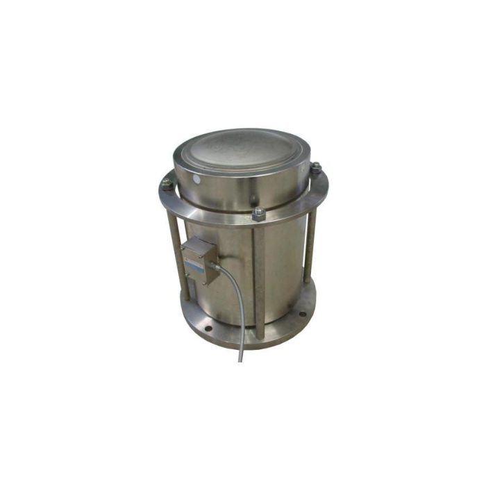

METRAVON MV-LC0001 is a compression column load cell for high-capacity weighing supports, with a nominal range of 10-1000 t. It is selected as part of the load-bearing assembly: the sensor, upper contact, lower seat and surrounding restraint must work together. A high capacity does not establish that an existing seat or support plate can be retained. Compare the rated outline and the complete installed height before choosing a replacement.
Choose the compression column load cell from the support reaction
For a platform, vessel or hopper, determine the largest reaction at each support from the actual structural arrangement and loading conditions. Dividing total contents by the number of sensors is not enough where reactions are unequal or external forces are present. Include the empty structure, operating load and relevant transient conditions in the assessment. The sensor rating does not provide the structural capacity of the foundation, supporting frame or restraint. Submit those interfaces with the required useful weighing interval.
Check column height and both contact diameters by rating
The metric table distinguishes body height A, lower-to-shoulder reference B and full vertical reference C, together with upper D, lower E and body F diameters. For example, the 30 t row gives C=120 mm and D/E/F=50/64/75 mm, while 100 t gives C=200 mm and D/E/F=109/96/126 mm. Do not reuse a seat based on the outer body diameter alone. Obtain the rated drawing for capacities not covered by a displayed dimensional row, including the 10 t end of the nominal range. Use a controlled metric drawing for machining, including the complete datum definitions.
| Item | Value | Selection notes |
|---|---|---|
| 30 t: C / D / E / F | 120 / 50 / 64 / 75 mm | Compare upper seat, lower support and the total column height. |
| 50 t: C / D / E / F | 125 / 54 / 68 / 87 mm | A similar body height does not establish identical seats. |
| 100 t: C / D / E / F | 200 / 109 / 96 / 126 mm | Check both contact interfaces before retaining platework. |
| 250-350 t: C / D / E / F | 280 / 150 / 175 / 205 mm | Use the confirmed rated row and complete assembly drawing. |
| 500-750 t: C / D / E / F | 350 / 175 / 199 / 260 mm | Include tool access and handling space beyond the body. |
| 1000 t: C / D / E / F | 493 / 160 / 280 / 340 mm | Do not extrapolate the upper contact diameter from a smaller row. |
Distinguish the bare column from the pictured mounting assembly
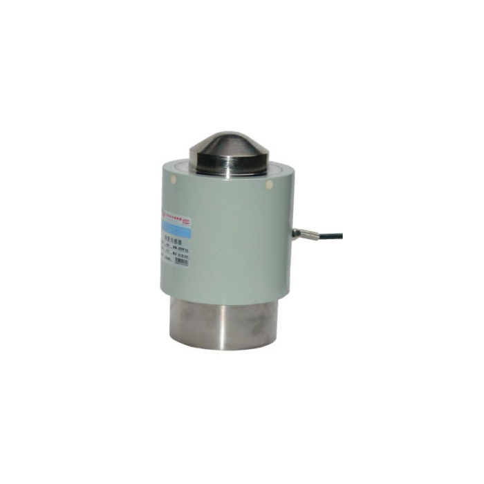
The reference photographs show both a column sensor and a surrounding plated assembly. They do not establish that the plates, rods, seats or restraints are included in every sensor order. Define the supplied items, their total stack height and how the load is centred into the contact surface. A self-centring description is not a quantified allowance for side load, travel or angular error. Any uplift restraint or lateral stop needs its own reviewed design and clearances; it must not bypass the measurement in normal operation.
Match the 1.5 mV/V bridge before retaining the indicator
The electrical reference is 1.5 +/-0.01 mV/V with 10-12 V DC excitation, 750 +/-20 ohms input resistance and 700 +/-5 ohms output resistance. Confirm the indicator excitation, input range and calibration method rather than assuming a 2.0 mV/V replacement. For a PLC process channel, specify a suitable bridge acquisition or conditioning stage. Obtain the delivered terminal functions: the reference colour list and circuit show inconsistent signal polarity, so colour copying alone is not a release method.
Verify the final support assembly under working conditions
Agree reference loading and record repeat response, unloaded return and any required position or corner checks for the completed structure. The listed precision is 0.05% FS and temperature effect is separately 0.05% FS per 10 deg C. Check the intended working increments and actual sensor temperatures against those full-scale entries. The operating range is -40 to +85 deg C. Confirm alloy steel or stainless steel and the delivered IP67/IP68 sealing version for the installation, not the stronger grade by default. The 200% FS safe-load entry does not approve a proof test of the complete scale or its support steelwork.
Mounting supply, retained indicators and installed accuracy
Q1. Are the pictured plates and restraint rods part of the standard sensor supply?
Their presence in a photograph does not define the offer. Request an itemised assembly drawing and quotation identifying the sensor, seats, plates, restraints and accessories, with the resulting installed height.
Q2. Can an existing 2.0 mV/V indicator retain its old calibration?
Check whether it supports the 1.5 mV/V bridge and specified excitation, then calibrate the completed support assembly. A configurable indicator may be usable, but the old span cannot be presumed correct.
Q3. Is 0.05% FS the accuracy of the complete installed weighing system?
It is a sensor specification entry, not a complete system guarantee. Structural contact, external forces, indicator performance and the acceptance method also affect installed results. Agree the system requirement and verify it through the final assembly.
