


 Chinese
 Spanish
 Russian
 Portuguese
 French
 German
 Indonesian
 Thai
 Vietnamese
 Arabic
 Italian
 Turkish
 Polish
 Japanese


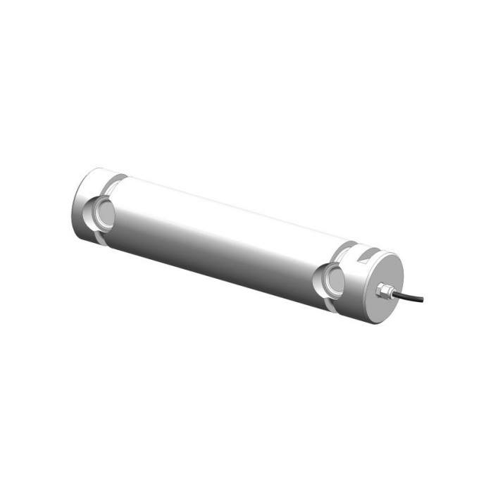

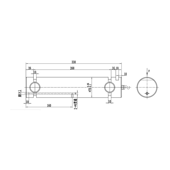
METRAVON MV-LC0009 is a long-body load pin with a 330 mm outline, a diameter-70 body reference and a technical range up to 10 t. The drawing contains longitudinal and cross-passage details in addition to the sensing regions. A useful enquiry must identify the member contacts, retention and any service route required by the joint. Neither the total length nor a visible passage establishes an approved support span or maintenance connection.
Place the long-body load pin in a complete joint section
The drawing has a 330 mm longitudinal dimension and a separate 268 mm reference between specified local datums. Two 10 mm sections are shown near the sensing regions. The diameter-70 body entry includes negative tolerances of -0.05 and -0.1 mm. Compare the actual bush widths, support contacts, loaded member and axial stops with the released drawing. Do not assume that the full 330 mm can be left unsupported or that any convenient length of the cylindrical body may carry a supporting bush.
Resolve the passage functions before connecting service hardware
The outline identifies an M8 x 1 entry, two diameter-6 through-passage details and a 160 mm locating reference. Those labels do not state a permissible lifting attachment, service pressure or fitting procedure. If a lubrication route or other service connection is needed, describe it and request confirmation of the passage functions, fittings and seals. If it is not needed, obtain the specified closure arrangement. Do not drill, tap or add a plug by inference from a small website drawing.
Separate the optional amplifier from the bridge specification
The detailed electrical table lists 1.0 +/-0.015 mV/V at 10-12 V DC, while the feature description mentions an optional built-in 4-20 mA amplifier. That mention does not provide a complete supply, wiring or scaling schedule for the amplified build. State whether the receiving equipment requires a bridge or a current loop and obtain the actual version documents. Do not assume the 24 V value listed for a different product, or inherit CAN and dual-channel options from neighbouring catalogue models.
| Item | Value | Selection notes |
|---|---|---|
| Technical load reference | Up to 10 t | Confirm the reaction and the complete rated contact arrangement. |
| Longitudinal references | 330 / 268 mm | These are distinct datums, not interchangeable support spans. |
| Body diameter | 70 mm | Use the negative fit tolerances and mating-bore specification. |
| Passage-related entries | M8 x 1; two 6 mm passages | Require the approved function, fittings and closure instructions. |
| Documented bridge | 1.0 +/-0.015 mV/V / 10-12 V DC | Use a suitable bridge input or defined conditioning system. |
| Optional amplified output | 4-20 mA mentioned | Supply, wiring and scaling must be confirmed for that version. |
Plan the cable and the inspection points around the mechanism
The cable exits at the end in the reference arrangement. Allow room to route and inspect it without using the cable as an axial restraint. Establish the direction mark relative to the real reaction and keep passage fittings or keepers away from the approved load contacts. Show how the joint is supported when the pin is removed for service. A long pin that cannot be withdrawn without major disassembly should have that maintenance requirement resolved before the surrounding bracket is fabricated.
Accept the measured reaction, not an assumed equipment capacity
Use agreed independent loads through the final joint and record the controller response, repeat readings and unloading return. Evaluate the required process increment against 0.5% FS precision and 0.5% FS per 10 deg C temperature effect. Confirm the -40 to +85 deg C interval, material selection and IP67 conditions at the completed cable and service connections. The sensor safe-load reference of 200% FS does not approve a particular bracket span, service fitting or equipment proof test.
Long spans, service entries and amplifier confirmation
Q1. Can the full 330 mm body bridge a wide gap?
The outline length is not an allowable unsupported span. Provide the actual member and bush positions and obtain the rated contact arrangement for that geometry and reaction.
Q2. Can M8 x 1 be used as a lifting or pulling connection?
A thread label alone gives no approved attachment function or allowable load. Obtain the designated purpose and safe handling procedure before attaching a tool or service fitting.
Q3. Is the optional amplifier automatically a 24 V unit?
The available model-specific description does not settle that supply. Require the quotation and connection schedule to identify the amplified version, supply, scaling and terminals before purchase.
Q4. Can a long-body pin retain the old display calibration?
Only after checking the delivered sensitivity, force direction and actual load introduction. Verify the final assembly with independent reaction references; matching the controller connector or nominal range is insufficient.
