


 Chinese
 Spanish
 Russian
 Portuguese
 French
 German
 Indonesian
 Thai
 Vietnamese
 Arabic
 Italian
 Turkish
 Polish
 Japanese


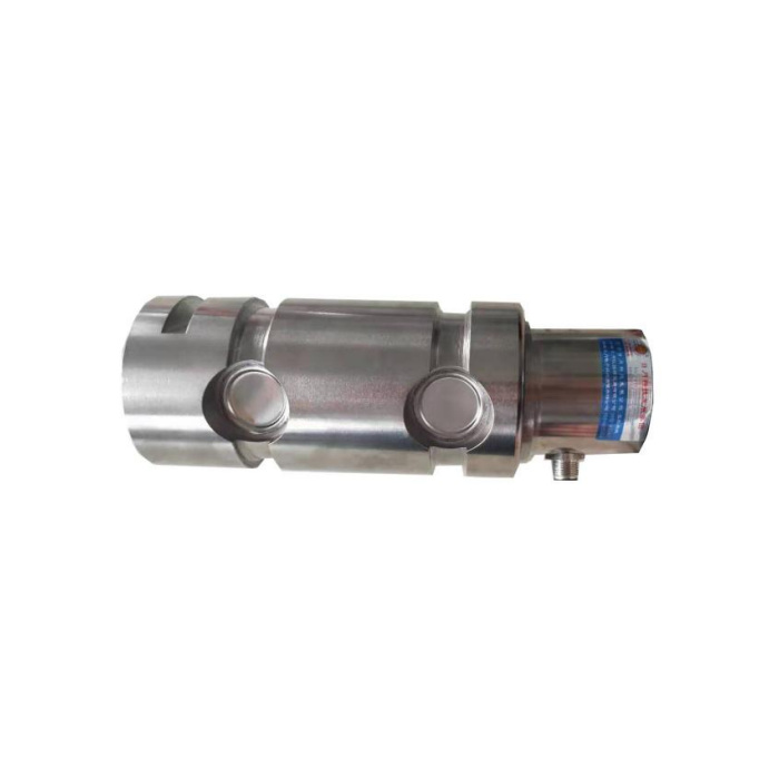

METRAVON MV-LC0015 is a stepped load pin with diameter-80 bearing lands, a reduced diameter-57.5 end section and a side connector visible on the reference photograph. Its technical maximum is 60 t. The stepped shape can affect insertion, support and electrical access, so the enquiry should show the surrounding bracket as well as the pin. The reduced end must not be treated as an extra support surface without an approved rated arrangement.
Compare shoulders and supports before considering an old-pin replacement
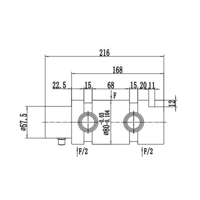
The outline gives a 216 mm longitudinal dimension and a 168 mm secondary reference. It also shows two 15 mm relieved sections and a 68 mm central reference between them. The diameter-80 lands have their own negative tolerances; the reduced end is a different mechanical region. Show where each bush starts and ends and whether a shoulder contacts a spacer or keeper. A stepped replacement that enters the bore can still place the reaction on the wrong part of the body.
| Item | Value | Selection notes |
|---|---|---|
| Technical maximum reference | 60 t | Agree the rated joint, not only a matching shaft outline. |
| Main / reduced-end diameters | 80 / 57.5 mm | Assign contact and housing-clearance functions separately. |
| Longitudinal references | 216 / 168 mm | Include the full datum chain and axial removal access. |
| Central / relieved dimensions | 68 / 15 mm | Both 15 mm sections need placement on the assembly section. |
| Connection arrangement | Side connector at reduced end | Provide radial room for the delivered mating plug. |
| Wiring release requirement | Build-specific terminal schedule | Resolve the signal-colour conflict before connecting power. |
Leave radial access for the side connector
The reference photograph and drawing place the electrical connection at the reduced end, projecting from the side. Plan plug diameter, cable departure and access for removal in addition to the axial insertion space. Include the nearby frame or guard in the installation sketch. Do not rotate the pin away from its approved sensing direction simply to fit a cable, and do not use a plug body as a mechanical stop. Any different connector position needs confirmation as part of the supplied version.
Obtain one consistent connection record before reconnecting a cable
The displayed four-position legend identifies a black signal conductor, while the amplifier sketch identifies a white signal conductor. Those references are not a safe universal wiring instruction. Request the actual supplied circuit, terminal functions, connector view and cable record. First determine whether the item is bridge-only, amplified current or CAN. Bridge sensitivity is 1.0 +/-0.015 mV/V at 10-12 V DC; the 4-20 mA alternative lists 24 V DC. Applying the wrong supply or copying another option pinout can damage the interface.
Define channel behaviour with the receiving system
The reference lists CANopen and CANopen Safety alternatives and describes redundant signal possibilities. Select the actual output and obtain its channel count, scaling and fault behaviour before configuring a PLC or local monitor. For a dual-channel requirement, identify what the receiving controller must compare and what documentation the installation needs. A general bus name or redundant-output description does not certify a protective function, establish a safety level or replace validation of the complete equipment.
Check repeatability after the stepped joint is secured
Apply agreed reference loads through the final bracket and compare readings after tightening the approved retention, fitting guards and securing the cable. Recheck unloading return and the mechanism positions relevant to the measurement. The 0.5% FS precision and 0.5% FS per 10 deg C temperature entries must be considered against the useful reaction interval. Confirm alloy steel or stainless steel, IP67 connection conditions and the -40 to +85 deg C operating reference for the site. Keep the 200% FS safe-load figure separate from any equipment proof-load procedure.
Reduced-end support, wiring colours and connector clearance
Q1. Can a bush extend onto the reduced end?
Only if the approved rated drawing allows that contact. The smaller end and main lands are different regions. Extending a bush to use spare length can move the support and obstruct the connector.
Q2. Should the black or white conductor be connected as signal?
The reference legend and amplifier sketch disagree. Do not choose by colour alone. Use the connection schedule for the supplied output version and cable, then verify polarity and scaling under controlled loading.
Q3. Can the pin be rotated so that the connector clears the guard?
Cable clearance must be resolved without losing the specified measurement orientation. Submit the guard and bracket geometry and obtain an approved connector and retention arrangement rather than rotating the sensor by convenience.
Q4. What is needed to retain an existing two-channel controller?
Supply the controller input specifications and channel-checking requirements with the old connection record. The offered pin needs documented matching outputs, supplies and fault behaviour; two channels cannot be assumed from the catalogue options.
