


 Chinese
 Spanish
 Russian
 Portuguese
 French
 German
 Indonesian
 Thai
 Vietnamese
 Arabic
 Italian
 Turkish
 Polish
 Japanese



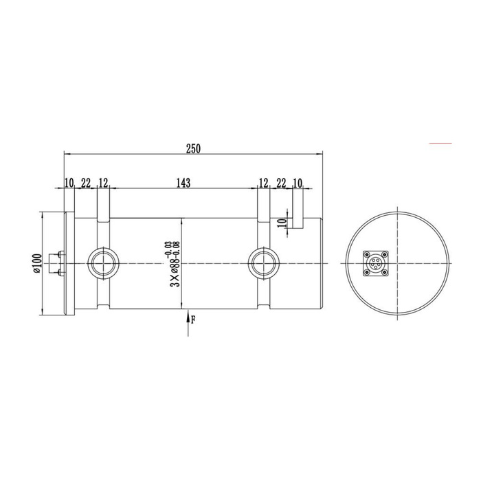
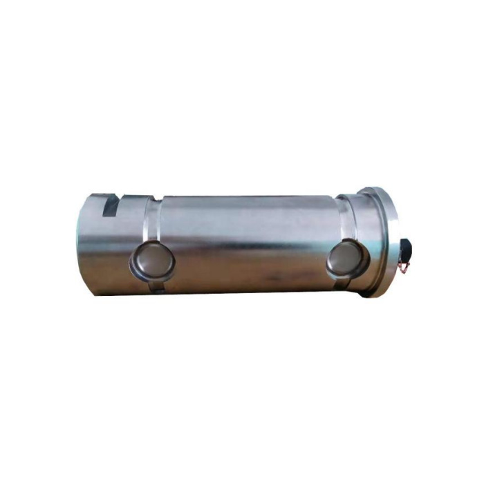
METRAVON MV-LC0016 is a load pin for measuring force within an existing or newly designed mechanical joint. The technical reference extends to 80 t and shows an end-mounted electrical connector. It is not selected simply by matching an old pin diameter: bearing widths, support positions, load direction and retention determine how the joint force reaches the sensing sections. Include those details with the required electrical output when requesting a replacement.
Match the load pin bearing positions to the joint section
The reference drawing marks a 250 mm longitudinal dimension, a diameter-100 end feature and three diameter-88 lands with negative size tolerances. Obtain the complete toleranced drawing rather than treating 88 mm as an unrestricted sliding fit. Show the central loaded member, outer supports, bushes, gaps and axial retention in a section through the joint. The drawing alone does not establish that one reference geometry suits every rating within the technical interval. A pin that passes through the bore can still have an unsuitable support span or force distribution.
| Item | Value | Selection notes |
|---|---|---|
| Technical load reference | Up to 80 t | Confirm the rated force and the joint geometry together. |
| Longitudinal drawing reference | 250 mm | Include connector and plug access beyond the mechanical datum. |
| Bearing-land reference | Three 88 mm diameter lands | Use the delivered tolerances and joint fit, not nominal diameter alone. |
| End-feature diameter | 100 mm | Check retention and insertion access in the joint section. |
| Bridge output / excitation | 1.0 mV/V / 10-12 V DC | Current and bus versions require their own electrical confirmation. |
| Precision / temperature effect | 0.5% FS / 0.5% FS per 10 deg C | Assess the useful force interval and actual sensor temperatures. |
Preserve the intended load direction and connector access
An F arrow in the outline defines a measurement direction relative to the body. Confirm how the pin is prevented from rotating away from that orientation and how axial movement is limited. Do not use the connector or cable as a rotation stop. Reserve space at the connector end for the mating plug, strain relief and service access. The connector face and rear views must be distinguished when preparing wiring; physical resemblance to an old socket is not sufficient confirmation of terminal functions.
Select one documented electrical build before applying power
The specification lists a 1.0 +/-0.015 mV/V bridge, a 4-20 mA/24 V DC option, and CANopen or CANopen Safety references. These are configuration choices, not proof that one supplied pin provides every interface at once. The bridge supply entry is 10-12 V DC and must not be replaced by the current-output supply. Ask the offer to state the actual interface, supply, connector, scaling and channel count. If two independent channels are required, their functions and fault behaviour need explicit documentation rather than an assumption based on the general redundant-output description.
Describe the pin reaction rather than only the lifted or carried weight
For a sheave, gate joint or lifting connection, provide the actual mechanism and force directions. A load pin measures the reaction transmitted through its bearing arrangement; that reaction must not automatically be equated to rope tension or payload. Specify the largest expected reaction, useful measurement interval and any changes of direction or contact position. Reference precision is 0.5% FS and temperature effect is separately listed as 0.5% FS per 10 deg C. Those full-scale entries need comparison with the actual operating temperatures and useful force changes.
Verify the installed joint without treating the pin as a certified safety system
Agree safe reference loads applied through the final joint and compare repeated loading, unloaded return and any relevant mechanism positions. Record orientation, bushes, retention and controller scaling with the results. A CANopen Safety option name does not establish an approved complete safety function or a particular safety integrity level. IP67, material choice and the -40 to +85 deg C operating interval also need checking against actual exposure. The 200% FS safe-load entry does not approve an overload test of the surrounding joint, hook, frame or lifting equipment.
Joint replacement, measured reaction and output selection
Q1. Can this replace an ordinary pin solely because the diameter matches?
No. Compare loaded and supporting member widths, gaps, bearing fits, retention and the measurement direction. The offered pin must be reviewed as part of that joint. A nominal diameter match does not establish the force path or calibration condition.
Q2. Does the pin display rope tension directly?
It measures the reaction at its joint. The relationship to rope tension or payload depends on the mechanism and force directions. Submit the sheave or connection arrangement and have the required conversion and acceptance method defined for the project.
Q3. Are bridge, current and CAN outputs all supplied together?
The reference lists alternative interface routes. Require the quoted build to identify the actual outputs, supplies and terminal assignments. If a dual-channel arrangement is needed, obtain its channel definition and verification requirements separately.
Q4. Is the CANopen Safety reference enough to approve a protective stop?
No complete safety-function approval follows from an interface name. Obtain the exact delivered option documents and have the complete sensor, controller and actuator function validated for the intended application. Do not infer a safety level or certification from this product description.
