


 Chinese
 Spanish
 Russian
 Portuguese
 French
 German
 Indonesian
 Thai
 Vietnamese
 Arabic
 Italian
 Turkish
 Polish
 Japanese


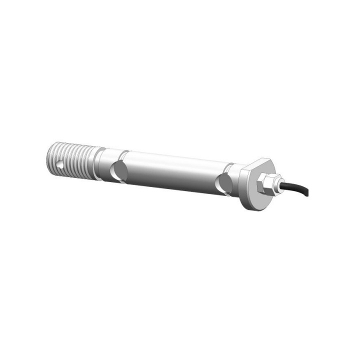

METRAVON MV-LC0017 is a compact load pin with a 650 kg technical reference, an M24 retaining-end callout and an axial cable outlet. It belongs to a much smaller load class than the tonne-rated pins in the same catalogue. For a small joint, the enquiry should identify the actual force carried by the pin, the bearing fits and how the end is retained. A threaded end does not turn it into a bolt-type tension sensor.
Check the 650 kg load pin against the actual joint force
Keep the rated unit explicit: the technical entry is in kilograms, not tonnes. The pin reaction can differ from a carried mass because of the mechanism geometry and force directions. Provide the joint section and operating positions rather than just a machine payload. Define the useful changes that the control system must recognise. The 0.5% FS precision entry and 0.5% FS per 10 deg C temperature effect are full-scale references, so a small indicated change should be assessed against that basis and the actual reader.
Use the retaining thread without changing the bearing condition
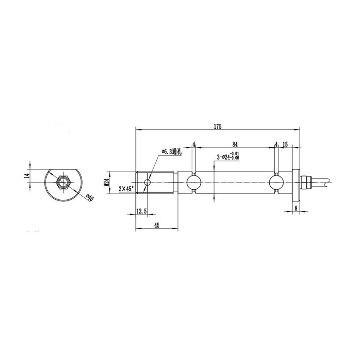
The outline shows M24 at the end, three diameter-24 lands with negative tolerances, a 175 mm longitudinal reference, an 84 mm inner reference and a diameter-6.3 through-hole near the retaining end. A diameter-40 end feature and further local dimensions are also shown. Obtain the controlled drawing for thread pitch, engagement, bore fit and the functions of the retaining features. Do not move a nut or spacer against an unintended shoulder so that it changes the support condition or forces the sensor to act as an axial tie.
| Item | Value | Selection notes |
|---|---|---|
| Technical load reference | Up to 650 kg | Do not transfer tonne-rated pin assumptions to this joint. |
| Retaining-end callout | M24 | Confirm pitch, engagement and the approved retention arrangement. |
| Bearing-land reference | Three 24 mm diameter lands | Use the controlled negative tolerances and mating-bore specification. |
| Longitudinal / inner references | 175 / 84 mm | Keep the complete datum chain with the joint section. |
| Retaining-end through-hole | 6.3 mm diameter | Confirm its function rather than assigning it a structural capacity. |
| Documented bridge channel | 1.0 mV/V / 10-12 V DC | An optional current-output version requires its own supply and wiring. |
Reserve cable access when the pin is inserted and removed
The cable exits along the pin axis at the opposite end to the retaining detail. Show the available axial space, gland clearance and route to the junction or reader. Retention should preserve the intended measurement orientation without twisting or pinching that cable. If the joint requires a different exit direction, obtain an approved mechanical and electrical configuration rather than bending the gland or modifying the pin. Any removal procedure needs a safe way to support the connected members before the sensing pin is released.
Keep the optional amplifier separate from the bridge specification
The detailed channel is a 1.0 +/-0.015 mV/V bridge excited at 10-12 V DC. The feature text mentions an optional built-in 4-20 mA amplifier, but it does not settle every supply and wiring detail for that option. Ask the quotation to identify whether the delivered item is bridge-only or amplified, with its supply, scaling and cable functions. Do not apply a process-transmitter supply to the bridge by assumption. The bridge colour list and circuit disagree on signal polarity, so use the delivered connection record and a controlled loading check.
Accept the small joint in its final retained condition
Use agreed reference loads through the actual joint, comparing loaded response and unloading return after the retention is secured. If adjustment of a spacer, nut or cable restraint changes the reading, investigate the mechanical cause before changing calibration. IP67 and material choice need comparison with actual cleaning, water and corrosion conditions; the operating interval is -40 to +85 deg C. A 200% FS safe-load entry is not a test instruction for the linkage or permission to use the retaining thread as an unsupported lifting attachment.
Retention, amplified outputs and changing zero
Q1. Can the M24 end be used to measure an axial bolt load?
The reference describes a load pin, not an approved bolt-tension transducer. Its bearing and loading arrangement must match the intended measurement. Obtain a separately approved configuration if the project needs axial tension or a lifting attachment.
Q2. Will the 4-20 mA option use the same wiring as the bridge?
Do not assume that it will. Specify the amplified version and obtain its actual supply, scaling and cable functions. The feature statement alone is not a complete installation schedule for the current-output build.
Q3. What should be checked if zero changes when the retaining nut is secured?
Check contact at shoulders, spacers and bushes, along with axial restraint and cable tension. Tightening may have altered the pin support condition. Resolve that mechanical change before accepting a new zero or span setting.
