


 Chinese
 Spanish
 Russian
 Portuguese
 French
 German
 Indonesian
 Thai
 Vietnamese
 Arabic
 Italian
 Turkish
 Polish
 Japanese


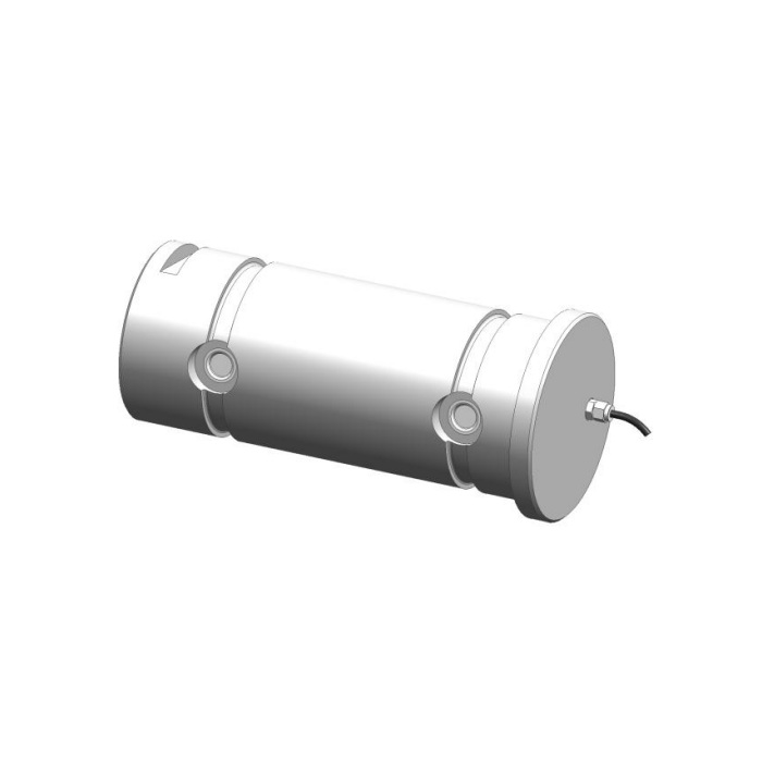

METRAVON MV-LC0018 is a load pin for heavy bearing-joint replacement, with a technical reference up to 150 t. Its outline uses a diameter-120 shaft and a larger end flange, but replacement suitability depends on where the mating members load and support that shaft. Record the existing bearing arrangement before selecting the rated pin. Reusing worn bushes or an incorrect support span can prevent an otherwise suitable sensing pin from giving a reliable installed reading.
Record the bearing-joint section before choosing the replacement load pin
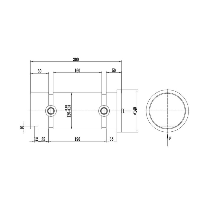
The outline shows a 300 mm longitudinal reference, a diameter-120 shaft with negative tolerances and a diameter-140 end feature. It also distinguishes a 160 mm inner reference from a 190 mm lower reference. These dimensions are not interchangeable definitions of a support span. Show the actual bush widths, loaded-member width, clearances and retention on the joint section. Confirm the selected pin drawing for that arrangement; a nominal maximum range does not approve every possible bearing separation.
| Item | Value | Selection notes |
|---|---|---|
| Technical maximum reference | 150 t | Confirm actual rated reaction and permitted bearing arrangement. |
| Longitudinal outline reference | 300 mm | Retain the complete joint and cable-access datums. |
| Shaft / end-feature diameter | 120 / 140 mm | Use the shaft tolerance and confirmed insertion/retention details. |
| Separate internal references | 160 / 190 mm | Neither number alone defines the project bearing span. |
| Bridge / current-output entries | 1.0 mV/V / 4-20 mA | These require different confirmed electrical builds. |
| Precision / temperature effect | 0.5% FS / 0.5% FS per 10 deg C | Test the actual joint across its useful operating conditions. |
Inspect wear and the orientation control before resetting the indicator
Check bushes, contact surfaces and retention under a safe unloaded condition. An F arrow defines the intended load direction relative to the pin features, and a flat or notch appears near the opposite end to the flange. Obtain the specified orientation and anti-rotation arrangement instead of assigning an arbitrary function or capacity to the visible notch. Never drill, grind or weld the sensing pin to make the old retainer fit. The surrounding joint must carry and retain the load without routing force through the cable or exit fitting.
Verify the reaction under the mechanism positions that matter
Give the maximum pin reaction and the directions or positions at which it occurs. A general lifting or port-equipment application reference does not establish the relationship between pin force, rope tension and payload for a particular mechanism. Agree reference loads and relevant positions through the completed bearing joint. Compare repeated readings and return after unloading, and record the final bushes and orientation. The listed 0.5% FS precision and 0.5% FS per 10 deg C temperature effect are sensor references, not an installed crane or gate measurement guarantee.
Select the delivered interface and document its channel behaviour
The electrical choices listed are a 1.0 +/-0.015 mV/V bridge, 4-20 mA/24 V DC, and CANopen or CANopen Safety. Confirm which build is supplied, with channel count, scaling, wiring and diagnostic information. The bridge excitation entry is 10-12 V DC. A generic redundant-interface statement is not proof of an approved dual-channel protective function. The reference bridge legend and circuit also differ in signal-colour polarity, so terminal functions must be verified from the supplied connection document before commissioning.
Keep exposure and structural acceptance separate from sensor overload data
Specify the actual environment at the shaft, cable entry and termination. IP67 does not, by itself, settle prolonged submersion, seawater corrosion or a pressure-washing procedure. Select alloy steel or stainless steel with the required exposure in mind, and compare sensor temperature with the -40 to +85 deg C operating interval. The 200% FS safe-load value belongs to the sensor reference. It cannot replace a safe acceptance procedure for the bearing housings, retention parts, frame or lifting equipment.
Where the connection requires a different end housing, compare the MV-LC0019 connector-end arrangement. Its nominal diameter does not establish compatibility with this longer reference; the support and signal-build checks remain separate.
Bore matching, worn bushes and retained controller settings
Q1. Is a matching 120 mm bore sufficient to accept the replacement?
It does not check bearing widths, loaded-member position, clearances, retention or orientation. Compare the controlled shaft fit and complete joint section. The maximum reaction must also be assessed for that actual support arrangement.
Q2. Can worn bushes remain while the sensor is replaced?
Review their condition and fit before deciding. Worn or displaced bearing contact can change how force is distributed through the pin. Replacing the electrical sensing element alone does not correct a mechanically unsuitable joint.
Q3. Can the same controller settings be copied from the old pin?
First confirm the supplied interface, rating, scaling and terminal functions. Then check readings through the final installed joint. A common signal name or an empty zero does not establish the correct loaded calibration.
