


 Chinese
 Spanish
 Russian
 Portuguese
 French
 German
 Indonesian
 Thai
 Vietnamese
 Arabic
 Italian
 Turkish
 Polish
 Japanese


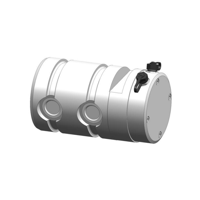

METRAVON MV-LC0019 is a load pin with a connector-end housing and a technical reference up to 250 t. Its electrical build and connector arrangement should be identified at the same time as the joint geometry. A cable that mates mechanically is not proof of compatible power or signal assignments. For an instrumented heavy joint, request one confirmed mechanical drawing and connection schedule for the actual supplied version.
Specify the load pin output before choosing the controller channel
The reference lists a 1.0 +/-0.015 mV/V bridge, a 4-20 mA/24 V DC route and CANopen or CANopen Safety options. Do not order a generic signal list and leave the hardware choice until installation. State what the receiving PLC, RTU or local load display can actually read. Confirm supply, scaling, number of channels and any external conditioner. A current or CAN version must not inherit the bridge 10-12 V DC entry without a build-specific electrical schedule.
Obtain the connector view and pin assignment for that same build
The reference contains a four-position connector legend and an amplifier sketch, but their signal-colour descriptions are not consistent. They are not a universal pinout for bridge, current and bus configurations. Ask for connector designation, mating-face orientation, keying, terminal functions and the required cable assembly. Do not wire a terminal marked ground as protective earth without its defined function. Confirm the sealing condition with plugs fitted and the treatment of any unused connection, rather than deriving IP67 performance from the unmated connector appearance.
Leave room for the end housing without moving the supports
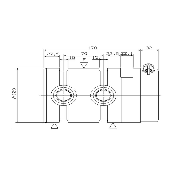
The mechanical outline carries a diameter-120 reference, a 170 mm longitudinal datum and a further 32 mm end section. It shows the F load position and two support symbols in a specific arrangement. Do not treat the whole end housing as an additional bearing surface or shift a bush onto it to make a short joint fit. Provide the joint member widths, support positions, retention, connector access and expected movement for review. The rated drawing must establish which surfaces carry force and which only enclose the electronics or connection.
| Item | Value | Selection notes |
|---|---|---|
| Technical load reference | Up to 250 t | Require a rating approved for the actual support geometry. |
| Mechanical diameter reference | 120 mm | A shared nominal diameter does not prove compatibility with another pin. |
| Longitudinal / end-section references | 170 / 32 mm | Allow for the housing, plug and cable beyond the approved support span. |
| Bridge / current-output routes | 1.0 mV/V / 4-20 mA | Specify the selected build and its exact supply and scaling. |
| Bus references | CANopen / CANopen Safety options | Obtain the actual profile and option documentation; no safety level implied. |
| Connector release requirement | Build-specific mating view and pinout | Reconcile the connector legend, amplifier wiring and delivered cable. |
Define channel checking without assuming a certified safety function
If the project needs more than one measurement channel, obtain the delivered channel definition, independence information, scaling and fault reporting. Agree how the controller should detect a lost or implausible measurement, based on those documented functions. The general redundant-output description and a CANopen Safety option name do not establish a complete certified protective function. Any safety use needs the actual option documentation and validation of the entire system; no safety level or certification is promised by the mechanical pin rating.
Verify the joint and the received signal together
Apply agreed reference loads through the final installed joint and compare the physical load reference with the controller indication, repeat response and unloading return. Record the supplied signal build, connector cable, bearing positions and orientation. The 0.5% FS precision entry and 0.5% FS per 10 deg C temperature effect need to be assessed at the useful working loads and temperatures. Check the actual pin temperature against the -40 to +85 deg C operating reference and choose alloy steel or stainless steel for the joint environment. The sensor 200% FS safe-load figure is not an overload-test target for the joint or equipment.
For a longer bearing-joint reference, review the MV-LC0018 installation discussion. A shared nominal diameter cannot replace comparison of the bearing positions, end access, retention and actual rating.
Connector reuse, end clearance and channel definition
Q1. Can a four-pin cable from an old sensor be reused?
Only after comparing connector identity, keying, terminal functions, electrical build and environmental requirements. The displayed four-position legend is not a common pinout for every listed signal option. A matching shell is insufficient.
Q2. Does the 32 mm end section belong inside the supporting bush?
Do not assume it is a bearing surface. Confirm the approved support positions and housing clearance on the rated section. Moving a bush onto the end section can change the force path and prevent connector access.
Q3. Can this replace the diameter-120 MV-LC0018 without further checks?
The longitudinal references, end arrangement, rating and connections differ. Compare the joint drawing and required signal build, not just the nominal shaft diameter. No direct replacement relationship is established.
Q4. What must be supplied for a dual-channel monitoring enquiry?
State the controller inputs, required channel functions and how a fault should be handled, with the joint loads and geometry. Obtain the exact delivered architecture and test requirements. A general redundancy label is not enough to approve a protective function.
