


 Chinese
 Spanish
 Russian
 Portuguese
 French
 German
 Indonesian
 Thai
 Vietnamese
 Arabic
 Italian
 Turkish
 Polish
 Japanese


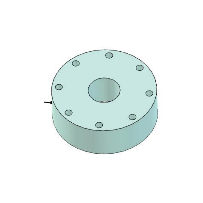

METRAVON MV-LC0020 is a spoke-type force load cell with a threaded centre and eight perimeter through-hole references. Its technical range is 30-10000 kN, expressed as force rather than tonnes. The centre connection, fixing circle, diameter and height change with rating. Choose the rated drawing before designing a test adaptor or weighing fixture; a shared round shape is not enough to define the contact arrangement or permissible force direction.
Select the spoke-type force load cell in kN before choosing the adaptor
The dimensional table is consistently force-rated. For example, 30 and 100 kN both use a 45 mm height and an M16 x 1.5 centre entry, but their outside diameters and fixing circles differ. At 200 kN the body becomes 180 mm in diameter with a 140 mm fixing circle and M30 x 3 centre. Do not treat a kN number as the same numerical tonnage or infer one common fixture from a shared thread. State the applied force, useful measurement interval and whether the assembly must work in more than one direction.
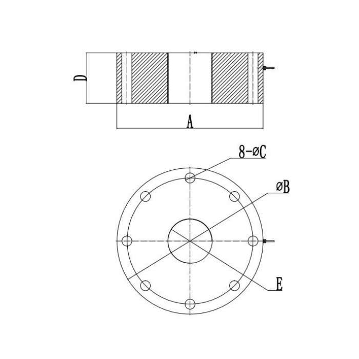
Keep the centre load fitting separate from the eight perimeter fixings
The outline labels eight diameter-C holes around a B fixing circle; E identifies the threaded centre connection. These features have different mechanical roles. Obtain the specified bearing faces, centre-adaptor engagement and perimeter support arrangement for the selected rating. The visible through-hole diameter is not an engagement depth or bolt-torque instruction. A threaded centre does not by itself approve lifting, repeated tension reversal or a suspended-load fixture. Require explicit load-direction approval and calibration for the actual adaptor design.
Check stack height and support stiffness when increasing the force rating
At 500 kN the reference diameter/height is 220/60 mm with an M45 x 3 centre. At 2000 kN those become 300/100 mm and M80 x 4. The 10000 kN row gives 580/200 mm and M180 x 6. The full fixture also includes the mating and supporting parts. Increasing capacity can therefore require changes to height, platework, adaptor and available tool access, not just a new instrument range. Use the actual rated row instead of scaling an existing part from the family maximum.
| Item | Value | Selection notes |
|---|---|---|
| 30 kN: outside / circle / height | 105 / 91 / 45 mm | Eight 10 mm holes; centre M16 x 1.5. |
| 100 kN: outside / circle / height | 120 / 102 / 45 mm | Same centre thread does not mean the same mounting pattern. |
| 200 kN: outside / circle / height | 180 / 140 / 45 mm | Eight 13 mm holes; centre M30 x 3. |
| 500 kN: outside / circle / height | 220 / 180 / 60 mm | Eight 18 mm holes; centre M45 x 3. |
| 2000 kN: outside / circle / height | 300 / 240 / 100 mm | Eight 22 mm holes; centre M80 x 4. |
| 10000 kN: outside / circle / height | 580 / 500 / 200 mm | Eight 40 mm holes; centre M180 x 6. |
Match the bridge and the useful force interval
The electrical specification is 2.0 +/-0.01 mV/V with 750 +/-20 ohms input and 700 +/-5 ohms output resistance at 10-12 V DC. Precision is listed as 0.03% FS, and temperature effect separately as 0.03% FS per 10 deg C. Compare these full-scale entries and the reader performance with the useful forces in the test or weighing process. Confirm delivered terminal functions, since the wire-colour list and circuit disagree in signal polarity. A PLC process input needs an appropriate bridge acquisition or external conditioning arrangement.
Accept the complete fixture under its intended loading conditions
Apply agreed independent force references through the final centre adaptor and supporting plate. Compare repeated loaded readings, unloading return and any required load directions or positions. Record fixture identity and the final reader settings. The operating interval is -40 to +85 deg C and the reference lists IP67/IP68 alternatives, so confirm the actual sealing and exposure conditions with the selected material. The 200% FS safe-load entry does not approve proof-loading the entire frame or operating the sensor beyond its nominal rating.
Shared threads, load direction and fixture upgrades
Q1. Can the 30 kN fixture accept a 100 kN sensor because both use M16 x 1.5?
Their height and centre-thread entries match, but the outside diameter and perimeter fixing circle do not. Compare the complete rated drawings and actual loading parts. A common thread does not approve a shared base or the higher-force fixture.
Q2. Does the threaded centre establish tension suitability?
Not without the approved load direction, adaptor engagement and supporting arrangement. State the required tension or compression operation and obtain the corresponding mechanical approval and calibration. Do not use the centre thread as an assumed lifting connection.
Q3. What should be checked when upgrading a force-test machine?
Check the largest force, useful measurement interval, frame and supporting-plate capacity, centre adaptor, stack height and reader. The sensor replacement must be accepted as part of the machine force chain, not only as a larger nominal range.
