


 Chinese
 Spanish
 Russian
 Portuguese
 French
 German
 Indonesian
 Thai
 Vietnamese
 Arabic
 Italian
 Turkish
 Polish
 Japanese



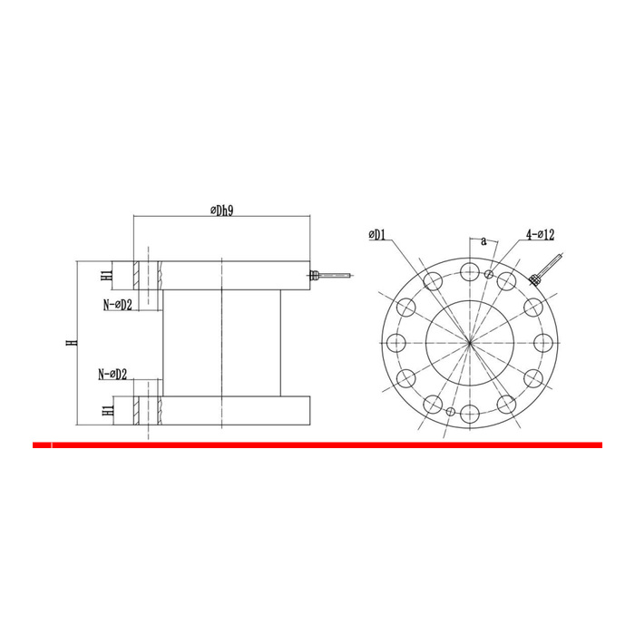
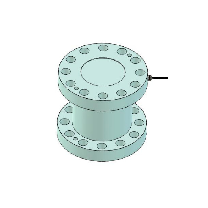
METRAVON MV-LC0021 is a double-flange compression load cell with a 40-300 t technical range. Its two end flanges connect the sensing element to a mechanical load assembly. Before ordering, compare both mating plates and the full axial space: the hole count, fixing diameters and sensor height change with rating. Check the complete rated flange pattern, bearing faces and assembled height before deciding which plates can be retained.
Lay out the double-flange compression load cell at the selected rating
The 40/60 t row gives H = 160 mm, flange diameter D = 197 mm and fixing-circle D1 = 160 mm, with twelve diameter-22 holes. At 100 t these references change to 230, 240 and 200 mm, with twelve diameter-26 holes. The 150/200 t group uses H = 326 mm and twelve diameter-33 holes; the 300 t row changes to eighteen diameter-33 holes and H = 358 mm. Do not make a universal mating plate by enlarging the holes of a smaller arrangement. Confirm the controlled pattern on both ends before fabrication.
| Item | Value | Selection notes |
|---|---|---|
| 40 / 60 t: H / D / D1 | 160 / 197 / 160 mm | Twelve 22 mm fixing holes in the main pattern. |
| 100 t: H / D / D1 | 230 / 240 / 200 mm | Twelve 26 mm holes; the smaller mating plate is not equivalent. |
| 150 / 200 t: H / D / D1 | 326 / 305 / 250 mm | Twelve 33 mm holes; confirm both end interfaces. |
| 300 t: H / D / D1 | 358 / 415 / 360 mm | Eighteen 33 mm holes; use the rated orientation view. |
| Bridge input / output resistance | 750 +/-20 / 700 +/-5 ohms | Check the reader, excitation burden and final calibration. |
| Sensor precision / temperature effect | 0.3% FS / 0.03% FS per 10 deg C | Neither entry defines the error of the complete project assembly. |
Distinguish the main fixing circle from auxiliary features
The outline also carries a four-position diameter-12 callout and an angular a reference. Those features must not be substituted for the main N x D2 fixing pattern. Have the rated drawing identify their function, orientation and relationship to the mating assembly. The a values are drawing orientation references, not a complete instruction for spacing every hole. Request the approved bearing faces, flange support and tightening procedure. Neither hole diameter nor the visible number of fixings establishes a permitted bending moment, lateral load or tensile rating.
Plan the mating plates and removal space together
Provide an axial section showing both end plates, fasteners and any locating shoulders, with the maximum compression and possible external forces. H is the sensor height reference; the final stack includes the project hardware. The cable leaves near the upper flange, so reserve access without trapping it between mating parts. If the structure can expand or move, show how guides and restraints carry those loads. A general self-centring description does not approve forced flange misalignment or permit the sensor to become the sole structural guide.
Use the actual bridge specification when retaining an instrument
The electrical entry is 2.0 +/-0.01 mV/V at 10-12 V DC excitation, with 750 +/-20 ohms input and 700 +/-5 ohms output resistance. Confirm the channel capacity and terminal functions for the delivered unit. The reference colour list and circuit disagree about signal polarity, so a copied colour legend is not a reliable installation instruction. Reference precision is 0.3% FS, while temperature effect is separately listed as 0.03% FS per 10 deg C. Do not substitute the smaller precision figures of other column models or retain an old calibration without testing this assembled fixture.
Agree loaded verification and exposure before release
State the useful force interval and the reference method available for the heavy assembly. Compare repeated loading and unloaded return with the final mating plates and constraints fitted. The operating interval is -40 to +85 deg C, but the sealing descriptions include IP67 and IP67/IP68 entries; confirm the supplied protection and exposure conditions on the offer. Alloy steel and stainless steel are listed alternatives. The 200% FS safe-load entry concerns the sensor, not an approval to proof-load the complete flange assembly.
Flange identity, auxiliary holes and quotation scope
Q1. Can a 100 t unit replace a 60 t unit on the existing plates?
Not on the same dimensional pattern. Overall height changes from 160 to 230 mm, flange diameter from 197 to 240 mm and fixing-circle diameter from 160 to 200 mm. The twelve main holes also change from 22 to 26 mm. Check both mating plates, bearing faces and the available stack height against the selected rated drawing. A higher sensor rating does not approve the old plates or fasteners for the higher reaction.
Q2. Can the four small holes replace the larger fixing pattern?
The four-position diameter-12 callout is separate from the main N x D2 pattern. Obtain its function and the approved mounting procedure on the rated drawing. Do not move the structural reaction to those features without explicit approval.
Q3. What should be sent for a flange-assembly quotation?
Send the selected load, both mating-plate drawings, available stack height, external-force description and intended reader. Include the proposed loaded verification method and exposure. Ask the offer to distinguish the sensing element from all fixture plates and fasteners.
