


 Chinese
 Spanish
 Russian
 Portuguese
 French
 German
 Indonesian
 Thai
 Vietnamese
 Arabic
 Italian
 Turkish
 Polish
 Japanese



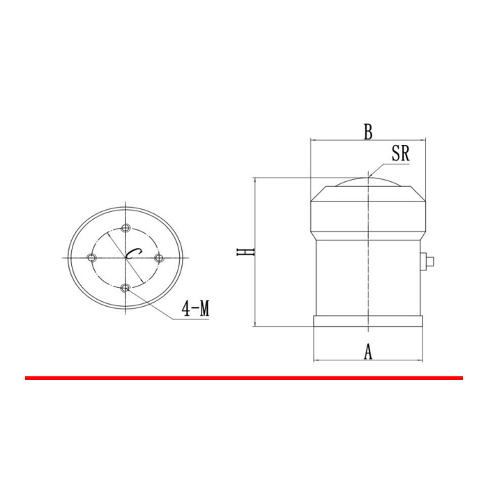
METRAVON MV-LC0022 is a curved-top compression load cell with a four-position base fixing arrangement. The technical range is 0.2-100 t, but it covers three different reference envelopes rather than one universal support. Its rated sensitivity is 1.5 mV/V, not the 2 mV/V used by several other METRAVON column models. Select the mating top seat, base detail and reader configuration for the same rated unit.
Pair the curved-top compression load cell with its actual seat
The lowest outline group, 0.2-7 t, gives H = 88 mm and SR = 30 mm. The 10-30 t group changes these to 130 and 50 mm, and the 50-100 t group to 178 and 80 mm. SR is the upper curved-contact reference, not another sensor height or a permissible rocking distance. Ask for the mating seat section and allowed contact condition. A pocket that accepts the cylindrical portion does not by itself confirm the upper contact fit.
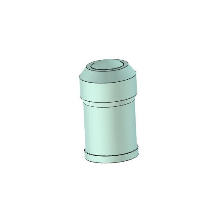
Check the four-position base independently of the top profile
The small group has A/B/C references of 60/65/38 mm and a four-M6 entry. The middle group uses 86/92/56 mm and four M8 positions; the largest group uses 118/126/90 mm and four M10 positions. C belongs to the fixing-circle view, while A and B identify different body-end dimensions. Obtain pitch, engagement, support-face and tightening details for the offered build. Do not use the top diameter as the base circle or treat the four fasteners as an approved uplift system.
| Item | Value | Selection notes |
|---|---|---|
| 0.2-7 t: H / SR | 88 / 30 mm | A/B/C = 60/65/38 mm; four-M6 reference. |
| 10-30 t: H / SR | 130 / 50 mm | A/B/C = 86/92/56 mm; four-M8 reference. |
| 50-100 t: H / SR | 178 / 80 mm | A/B/C = 118/126/90 mm; four-M10 reference. |
| Rated output / excitation | 1.5 mV/V / 10-12 V DC | Do not retain an unsuitable 2 mV/V span setup. |
| Input / output resistance | 400 +/-20 / 350 +/-5 ohms | Review the intended reader and connected support count. |
| Precision / temperature effect | 0.02% FS / 0.02% FS per 10 deg C | Use the full-scale basis when judging useful net increments. |
Assess the useful reading interval at the chosen full scale
Reference precision is 0.02% FS, with a separate temperature-effect entry of 0.02% FS per 10 deg C. For a weighing support, state tare, maximum contents and the smallest net change that needs to be recognised. Check the worst individual reaction where the load is shared. A broad family interval does not mean every intermediate rating is stocked or that one calibration covers all capacities. In particular, the reference outline groups do not define every rating between their labelled intervals; obtain a selected rated drawing rather than interpolating a missing row.
Configure the 1.5 mV/V bridge before loading the assembly
At 10-12 V DC excitation, the documented rated output is 1.5 +/-0.003 mV/V. Input resistance is 400 +/-20 ohms and output resistance 350 +/-5 ohms. A reader set up for another sensitivity needs checking and calibration, even if its empty display can be zeroed. Use delivered terminal functions because the signal-colour legend conflicts with the circuit. For a PLC process input, specify a compatible weighing conditioner or strain-gauge acquisition channel rather than assigning current-loop output to the raw sensor.
Accept the support with its final base and seat
Use the agreed reference loads through the actual top contact, comparing repeated readings and unloading return. Observe whether guides, guards or cable restraint alter the empty indication when connected. The feature list says IP67 while the technical table lists IP68, so confirm the offered enclosure rating and actual exposure instead of selecting the stronger entry by default. Operation is listed over -40 to +85 deg C, with alloy-steel or stainless-steel alternatives. Keep site structural verification separate from the 200% FS sensor safe-load entry.
Curved contact, reader settings and unlisted ratings
Q1. Does the curved top permit movement of the supported structure?
Permitted displacement or tilt depends on the mating seat and the approved assembly. SR only defines the curved profile in the reference outline. Supply the actual movement requirement for review, together with the guides and any lift-off restraint.
Q2. Will an existing 2 mV/V indicator setting remain correct?
The documented sensitivity here is 1.5 mV/V. Verify that the reader can excite and measure this bridge, then calibrate with the final seat and base fitted. Zeroing an empty display does not check the loaded scale factor.
Q3. Can a rating between two outline groups be dimensioned by interpolation?
The listed groups do not approve an interpolated body or thread arrangement. Ask for the exact offered rated unit and its drawing before making a base or seat. The technical range alone is not a complete list of available mechanical builds.
