


 Chinese
 Spanish
 Russian
 Portuguese
 French
 German
 Indonesian
 Thai
 Vietnamese
 Arabic
 Italian
 Turkish
 Polish
 Japanese


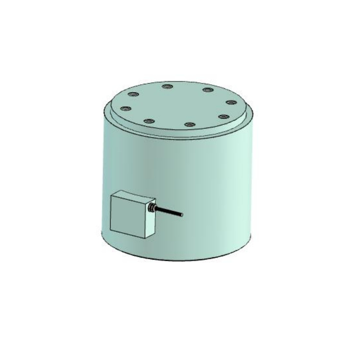

METRAVON MV-LC0023 is a 600 t compression load cell for a heavy force-measurement assembly. The reference specifies a single nominal rating, not a selectable range ending at 600 t. Its 1.5 mV/V bridge and the mechanical bearing arrangement need to be accepted together. A structural fixture capable of transmitting the force safely is a separate requirement from the electrical calibration of the sensor.
Define the 600 t compression load cell bearing arrangement first
Send an axial section of the upper loading part, lower support and any guides. Identify the force at the sensor, the useful operating interval and how bending or sideways reactions are kept out of the intended compression path. The cylindrical illustration does not establish that every visible cover surface is a permissible bearing face. Neither a general self-centring statement nor the nominal rating supplies an allowed tilt or restoring force. Require the approved contact areas and structural responsibilities on the assembly drawing.
Resolve the fixing layout before drilling or choosing bolts
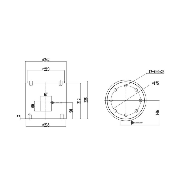
The outline includes 225 mm overall and a separate 212 mm vertical reference, together with diameter callouts of 242 and 236 mm in the side view. These are not a complete manufacturing specification. The plan shows a 175 mm circle and carries a 12-M20 x 25 callout, while the visible schematic hole count does not settle the allocation between the two ends. Obtain the controlled top and bottom patterns, thread definitions and fixing functions. The offer needs to define usable engagement, fastener grade and tightening requirements; the shorthand alone does not approve the fixture strength.
| Item | Value | Selection notes |
|---|---|---|
| Nominal reference rating | 600 t | Other nominal capacities require separate confirmation. |
| Overall-height annotation | 225 mm | Confirm bearing datums and complete fixture stack height. |
| Separate vertical reference | 212 mm | It is not interchangeable with the overall annotation. |
| Side-view diameter references | 242 / 236 mm | Use the approved top and bottom views before machining. |
| Signal / input / output resistance | 1.5 mV/V / 400 / 350 ohms | Check exact tolerances and reader suitability for the delivered unit. |
| Precision / temperature effect | 0.3% FS / 0.03% FS per 10 deg C | State useful loads and a suitable independent force-reference method. |
Specify the 1.5 mV/V channel and its acceptance interval
Rated output is 1.5 +/-0.01 mV/V with 10-12 V DC excitation, 400 +/-20 ohms input and 350 +/-5 ohms output resistance. Confirm the intended reader rather than carrying over settings from a 2 mV/V unit. The precision entry is 0.3% FS and the separate temperature effect is 0.03% FS per 10 deg C. If the task concerns a small change while a large dead load is present, state that change explicitly and assess the complete measurement chain. A nominal high-force rating does not establish the installed resolution or uncertainty at a small fraction of full scale.
Plan heavy-force verification without using failure limits as test targets
Agree a safe method of applying and independently checking the required forces through the final fixture. Record loading, unloading and repeat readings with the actual bearing parts, then retain the sensor identity and instrument settings with those results. The 200% FS safe-load entry is not an instruction to overload the fixture, and higher yielding or breakage entries are not usable measurement ranges. The enclosure references include IP67 and IP67/IP68, so obtain the supplied version and exposure conditions. Also specify material and sensor temperature against the listed -40 to +85 deg C operating interval. Delivered terminal functions must resolve the conflicting signal-colour legend before testing.
For a 500 t reference with a different bridge specification, review MV-LC0024. Comparing the two means checking useful force measurement, reader settings and the complete fixture; neither rating establishes an interchangeable mounting assembly.
Fixture approval and useful force measurement
Q1. Does the 600 t rating approve the bolts and loading plates?
It specifies the sensor reference, not the complete fixture. Bearing areas, bolts, plates, foundation and restraint need their own approval for the project loads. The order should identify which organisation supplies and verifies each part.
Q2. Can the mounting holes be machined from the displayed outline?
Obtain a controlled drawing first. The fixing callout needs a confirmed count and allocation at each end, with thread engagement and bearing faces defined. A small schematic image is not sufficient authority for a heavy-force fixture.
Q3. Can this be used to measure a small process change under a large preload?
Define both the preload and useful change, then compare them with the full-scale precision basis, reader performance and test method. A large nominal rating alone does not settle that measurement task. Agree acceptance at the actual working points rather than only at full scale.
