


 Chinese
 Spanish
 Russian
 Portuguese
 French
 German
 Indonesian
 Thai
 Vietnamese
 Arabic
 Italian
 Turkish
 Polish
 Japanese


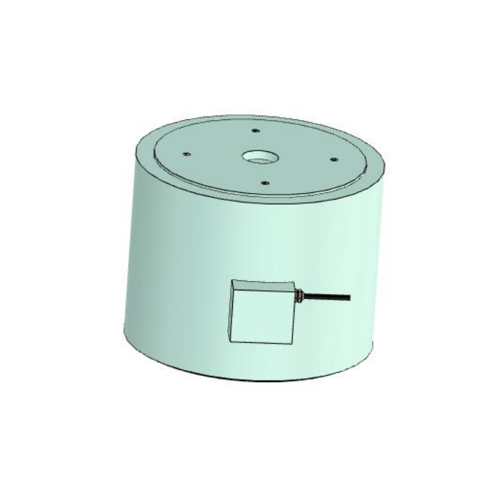

METRAVON MV-LC0024 is a 500 t compression load cell with a 2 mV/V bridge reference. For a high-load assembly, the first measurement question is often not whether it can display the maximum force, but whether it can distinguish the changes that decide the process. State that useful interval alongside the largest compression and the proposed loading fixture. The sensor rating does not by itself approve the surrounding bearing structure.
Judge the 500 t compression load cell against useful force changes
The specified precision is 0.2% FS, with a separate 0.05% FS per 10 deg C temperature-effect entry. These are full-scale references, not the same percentages of every indicated value. List the minimum and maximum working loads, any dead load, and the force changes that trigger an action. Ask for acceptance points spanning those actual conditions. A stable empty reading or many display digits is not evidence that a small change under heavy preload is measured with the required uncertainty.
| Item | Value | Selection notes |
|---|---|---|
| Nominal rating | 500 t | The fixture and its retention have separate structural requirements. |
| Precision basis | 0.2% FS | Compare useful changes against full scale, not only display resolution. |
| Temperature-effect reference | 0.05% FS per 10 deg C | Include expected sensor temperature changes in the test plan. |
| Rated bridge output | 2.0 +/-0.005 mV/V | A nominal sensitivity match does not approve a replacement. |
| Input / output resistance | 400 +/-20 / 350 +/-5 ohms | Check excitation and readout compatibility independently. |
| Mounting release requirement | Controlled top, bottom and section views | Resolve diameters, contact datums and fixing allocation before manufacture. |
Request one consistent mounting drawing before releasing the fixture
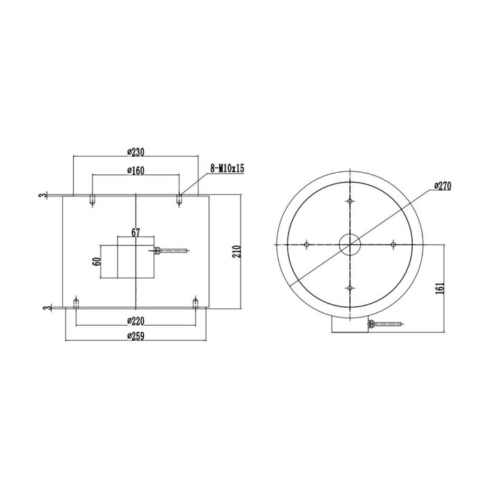
The outline shows a 210 mm vertical reference, but the different views contain several diameter annotations and distinct upper and lower fixing references. Do not select one outside diameter from the illustration as a complete pocket or adaptor specification. Obtain top, bottom and section views with bearing datums, tolerances, centre features and assembly height reconciled. The 8-M10 x 15 callout also needs its end allocation, thread definition and intended fixing function confirmed. Specify engagement and tightening from the approved assembly rather than assuming a permissible clamp force or load path through every screw.
Keep bearing and retention functions clear in the assembly section
Mark where the upper and lower structures apply the normal compression, and how lateral forces or uplift are restrained. A central feature in a rendered image is not evidence of a fluid port, lifting eye or calibrated through-bore arrangement. Do not use the lateral enclosure as a stop or handle for the heavy load train. If mounting or guides must allow thermal movement, specify that condition to the mechanical designer. No universal movement allowance or restoring action is quantified by the family description.
Check the bridge independently of the mechanical fixture
The reference output is 2.0 +/-0.005 mV/V at 10-12 V DC, with 400 +/-20 ohms input and 350 +/-5 ohms output resistance. Provide the reader and any other connected sensors so the excitation and input requirements can be checked. A shared nominal 2 mV/V label does not make the 500 t unit interchangeable with a different model. Resolve delivered wiring functions before a controlled compression-sign test; the reference colour legend and circuit disagree. Record calibration with the final bearing and fixing arrangement, not a temporary bench contact.
Close the project with loaded evidence and an agreed exposure specification
Use an independent force reference and a safe fixture procedure suited to the required working points. Compare repeated loading and return after removal, recording the sensor identity, contact parts and instrument setup. Never derive a site overload test from the 200% FS safe-load entry. Materials are listed as alloy steel or stainless steel and operation as -40 to +85 deg C. The feature and parameter pages use different IP67/IP68 statements; specify the delivered sealing and actual water or cleaning exposure rather than assuming the stronger statement covers the installation.
The MV-LC0023 600 t reference uses a 1.5 mV/V channel and its own assembly requirements. Consider it only against the actual force and verification requirements, not as an automatic capacity upgrade on the existing fixture.
Useful increments, fixture drawings and verification
Q1. Will a high-resolution display prove that small force changes are accurate?
The number of display digits is only one part of the measurement chain. Compare the required increment with sensor full-scale precision, temperature behaviour, reader performance and the installed reference-load results. Test under the actual preload if that is where the process decision is made.
Q2. Can an adaptor be machined from the diameter shown in the rendered view?
No single rendered diameter establishes all of the mounting geometry. Request consistent top, bottom and section views, including the load-bearing surfaces and tolerances. Confirm the selected dimensions before releasing a heavy fixture for manufacture.
Q3. Is this interchangeable with the 600 t MV-LC0023?
A capacity comparison is not enough. The electrical sensitivities differ, and each assembly needs its own bearing and fixing confirmation. Check the useful measurement interval and complete load train rather than treating the larger rating as an automatic substitute.
Q4. What should an enquiry include when the force reference is not yet chosen?
State the working loads, useful increments and available test space, with the proposed loading structure and reader. Ask how the assembly can be verified safely at those points. Do not replace an unavailable verification method with a claim based only on the nominal sensor rating.
