


 Chinese
 Spanish
 Russian
 Portuguese
 French
 German
 Indonesian
 Thai
 Vietnamese
 Arabic
 Italian
 Turkish
 Polish
 Japanese



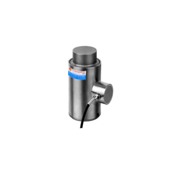
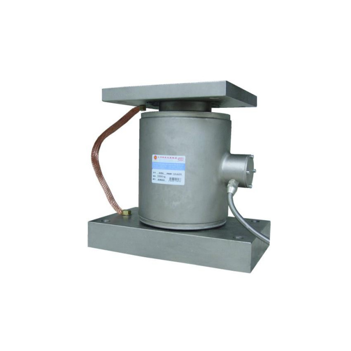
METRAVON MV-LC0025 is a compression column load cell with a 30-100 t technical range. Its reference views include both a bare sensor and a sensor between upper and lower plates. That distinction matters in a weighing-support quotation: the body dimensions do not describe the installed height or supply scope of every plated assembly. Decide which contact parts, base and upper plate are required before comparing prices or retaining existing hardware.
Separate the bare compression column load cell from the complete support
Identify whether the offer includes only the sensing body or also the upper contact, plates, fixing parts and any bonding provision required by the project. A photograph of an assembly is not an itemised scope of supply. The physical installation section should show the bearing faces of the delivered parts and the resulting height. Do not compare a bare-sensor quotation with a complete-support quotation as if they contained the same hardware or mechanical approval.
Match the curved top and two-position base on the rated drawing
The bare reference outline gives a diameter-89 body, a 160 mm overall-height annotation and a diameter-64 upper contact marked SR200. At the bottom it shows two M12 positions at 60 mm centres, with a 15 mm thread-depth callout. SR200 describes the curved surface, not a height or permitted travel. Confirm the matching upper seat and the base bearing detail for the offered rating. The supplied thread pitch, usable engagement and tightening procedure still need definition; a nominal depth does not mean every length of screw can be fitted safely.
| Item | Value | Selection notes |
|---|---|---|
| Published technical interval | 30-100 t | Confirm the selected rating and supplied support components. |
| Bare body / overall reference | 89 mm diameter / 160 mm height | These do not define every plated assembly height. |
| Upper contact / curved profile | 64 mm diameter / SR200 | Obtain the mating-seat detail and allowed contact condition. |
| Base fixing reference | Two M12 positions / 60 mm centres | Confirm pitch, engagement and approved bearing face. |
| Thread-depth callout | 15 mm | Use the actual fastener engagement, not an assumed screw length. |
| Bridge input / output resistance | 400 +/-20 / 380 +/-5 ohms | Match the reader and number of connected supports. |
Allow the plates and any retained parts to do their intended jobs
Show the actual vessel leg or platform structure, the location of any guides, and all retained contact components. Check whether a plate, shoulder or stop can divert force around the sensing element. A base fixing is not an automatic approval for a tension link or lift-off restraint. The assembly photograph includes a visible braided link, but its presence alone does not define the delivered electrical bonding scheme. Obtain the project connection and protection details rather than assigning that component a safety function from appearance.
Specify the reader and required net-weight behaviour
The bridge is listed at 2.0 +/-0.002 mV/V using 10-12 V DC, with 400 +/-20 ohms input and 380 +/-5 ohms output resistance. Provide support count, reader and any junction arrangement when requesting a complete weighing system. For integration to PLC or RTU process interfaces, specify the external weighing input or conditioner actually required. Confirm the delivered terminal functions because the colour legend and circuit differ on signal polarity. The 0.05% FS precision and 0.02% FS per 10 deg C temperature-effect entries need to be assessed against tare and useful material increments, not taken as a guarantee for the whole vessel.
Accept the final plated or bare configuration without changing it afterward
Apply the agreed reference loads through the supplied contact arrangement and compare repeated readings and unloading return. Keep the final plate set, guides and connected pipework in the test condition specified for the project. If those parts change, review whether calibration and acceptance remain valid. Confirm alloy steel or stainless steel, actual IP68 exposure and cable termination, and the listed -40 to +85 deg C operating interval. The 200% FS sensor safe-load figure is not a proof-load instruction for the support plates, vessel leg or base bolts.
Plate supply, installed height and retained hardware
Q1. Are the upper and lower plates included automatically?
The reference photograph does not settle supply scope. Ask the offer to list the sensor, contacts, plates, fasteners and required electrical accessories separately. Require a section showing the installed height of the quoted combination.
Q2. Can the assembly height be taken as 160 mm?
That is the bare reference height. Plates and contact parts can change the full bearing-to-bearing dimension. Supply the available gap and obtain the complete quoted assembly section before setting the vessel elevation.
Q3. Can existing platework stay if the base holes line up?
Check the upper seat, lower bearing surface, thread engagement and any restraint contacts as well as the hole pattern. The plates must transfer the intended compression without another force path. Alignment of two holes alone does not accept the complete retained support.
