


 Chinese
 Spanish
 Russian
 Portuguese
 French
 German
 Indonesian
 Thai
 Vietnamese
 Arabic
 Italian
 Turkish
 Polish
 Japanese


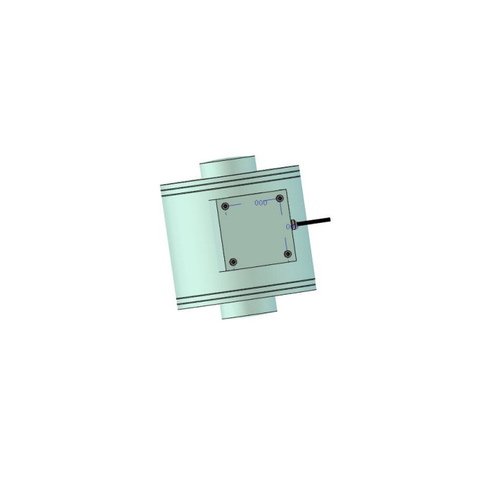

METRAVON MV-LC0026 is a double-ended column load cell for heavy compression weighing. Both ends have curved loading contacts, and the reference includes a separate seat outline. A suitable installation therefore needs two matched contact interfaces, not just a cylindrical body of the right tonnage. For a hopper, vessel or platform support, identify the selected rating, complete seat set and available loaded assembly gap before the base is fabricated.
Keep the double-ended column load cell within its stated technical range
The parameter sheet specifies 30-100 t, while the outline table contains additional rows below and above that interval. Those extra rows are not sufficient evidence of an offered range for this product. Within the stated interval, 30, 50, 70 and 100 t have separate dimensional references. Ask the offer to identify one rated row and its corresponding drawing. A table entry at 200 or 500 t must not be used to extend the technical specification or to quote a complete assembly without confirmation.
Compare both end profiles and the separate seat detail
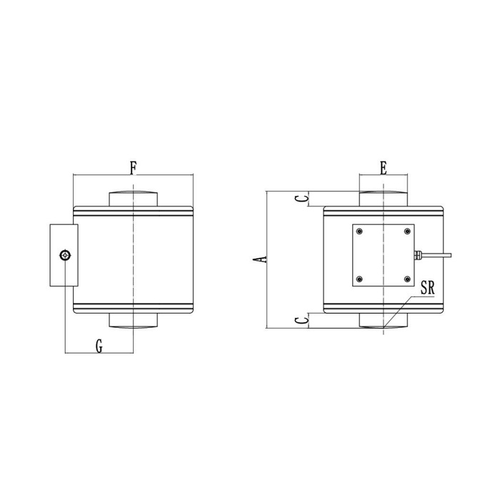
At 30 t, the reference gives overall A = 125 mm, body F = 100 mm, end E = 38 mm and SR = 150 mm. At 100 t these become 200, 175, 70 and 250 mm. SR describes the curved contact, not the installed height or allowable movement. The separate seat view has its own K, M, L and N dimensions. Confirm the seat contact profile, supporting face and included quantity with the rated assembly supplier; a seat cannot be selected only because its opening clears the projecting end.
| Item | Value | Selection notes |
|---|---|---|
| Published technical interval | 30-100 t | Do not extend the offered range from extra outline rows. |
| 30 t: A / F / E / SR | 125 / 100 / 38 / 150 mm | Read these letters with the sensor and separate seat views. |
| 50 t: A / F / E / SR | 155 / 125 / 49 / 200 mm | A complete seat assembly has its own installed height. |
| 70 t: A / F / E / SR | 182 / 145 / 59 / 250 mm | Confirm the matching upper and lower contact parts. |
| 100 t: A / F / E / SR | 200 / 175 / 70 / 250 mm | Equal SR does not establish the same body or seat size. |
| Bridge input / output resistance | 400 +/-20 / 380 +/-5 ohms | Include all connected supports in the indicator review. |
Measure the assembly gap with its actual contact parts
A is the sensor end-to-end reference. It is not automatically the bearing-to-bearing height after the seats and any base parts are added. Show both supporting structures and the upper and lower seat sections on the enquiry. Reserve space for the lateral enclosure and cable exit rather than fitting a tight circular pocket around F alone. Keep guards and restraints clear of the intended load path. The self-centring description gives no universal permissible angle or horizontal travel, so those requirements need explicit mechanical approval.
Review the 380-ohm output bridge with the complete weighing channel
The sensor is specified at 2.0 +/-0.002 mV/V, using 10-12 V DC excitation, 400 +/-20 ohms input resistance and 380 +/-5 ohms output resistance. Do not substitute the 350- or 700-ohm figures of a different column cell. Where several supports share an instrument, provide the number of bridges and the junction arrangement. Confirm delivered terminal functions and the response to controlled compression; the reference wire-colour list and circuit show conflicting signal polarity. An appropriate external conditioner is needed if the receiving controller expects a process-current or digital interface.
Test the seats in the final weighing arrangement
Check the largest individual support reaction, including vessel tare, contents and unequal loading, then define the useful net-weight changes and reference-load procedure. Precision is listed as 0.05% FS and temperature effect as 0.02% FS per 10 deg C; neither is a guarantee for an assembled vessel with unrestrained pipe forces. Compare repeated loading and unloading return after the final seats, guides and cable restraint are fitted. IP68 needs agreed exposure conditions and protected terminations. The -40 to +85 deg C operating interval and 200% FS safe-load entry do not establish an unrestricted washing procedure or a proof-load rating for the surrounding structure.
Seat reuse, range limits and assembly height
Q1. Does a 500 t outline row mean I can order this as a 500 t unit?
The technical entry for MV-LC0026 is 30-100 t. An extra dimensional row does not confirm a different supplied rating. Request a separate confirmed specification and assembly drawing before considering a capacity outside that interval.
Q2. Can the old lower seat be kept while only the upper one is changed?
Compare each retained seat with its actual mating end, condition and approved contact profile. The complete pair also determines installed height and movement. Reusing one part is acceptable only after that combination is confirmed, not because the empty sensor can be placed in it.
Q3. Which height should be used for a vessel support quotation?
Provide the available bearing-to-bearing gap and ask for the assembled sensor-and-seat height. The A dimension alone covers the sensor reference. Include any retained base, levelling or contact components so the quoted assembly fits the actual gap.
