


 Chinese
 Spanish
 Russian
 Portuguese
 French
 German
 Indonesian
 Thai
 Vietnamese
 Arabic
 Italian
 Turkish
 Polish
 Japanese


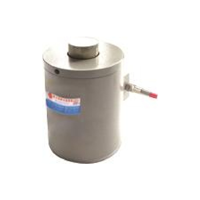

METRAVON MV-LC0027 is a compression column load cell with two M16 base fixing positions in its reference outline. It has a 20-60 t technical range and a raised upper loading contact. For a vessel leg or platform support, the base fixings locate the unit, while the approved bearing surfaces determine how the compression is carried. Treat those as separate checks when choosing a support or reviewing an existing plate.
Set the compression column load cell base from the correct pair of positions
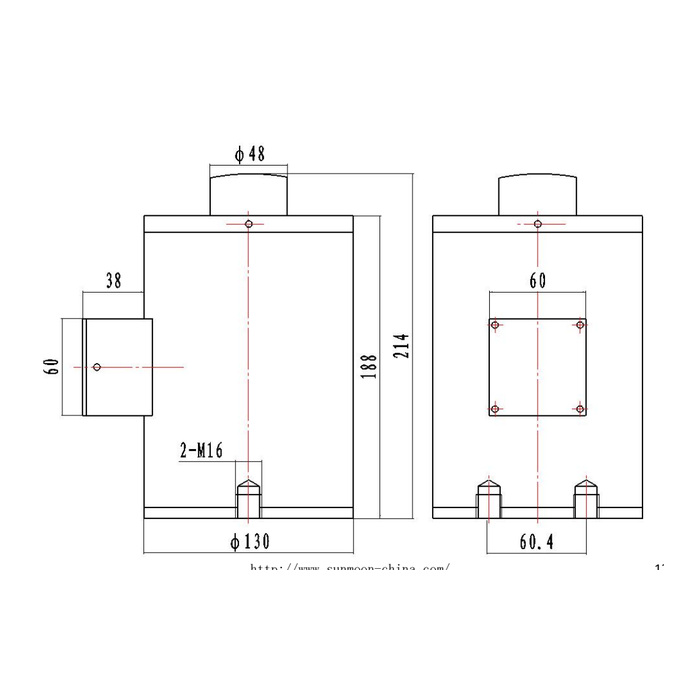
The lower view shows two M16 positions with a 60.4 mm centre-spacing reference. A separate 60 mm dimension belongs to the side cover and must not be used as the base pattern. Confirm the actual thread pitch, usable engagement, mounting face and fasteners for the selected rated build before machining an adaptor. The base threads do not by themselves approve a tensile attachment or a restraint that carries uplift through the sensing body.
| Item | Value | Selection notes |
|---|---|---|
| Technical load interval | 20-60 t | Request the exact offered rating and its dimensioned build. |
| Base fixing reference | Two M16 positions | Confirm pitch, engagement and approved support face. |
| Base centre spacing | 60.4 mm | The separate 60 mm cover dimension is not this fixing pattern. |
| Overall / body-height reference | 214 / 188 mm | Add the actual mating seat and retained support parts. |
| Body / upper-contact diameter | 130 / 48 mm | Check contact geometry and side-enclosure clearance. |
| Signal and excitation | 2.0 mV/V / 10-12 V DC | A suitable bridge reader or conditioner is required. |
Reserve the full height and the lateral enclosure clearance
The main body is diameter 130 mm. The vertical drawing references are 188 mm for the body and 214 mm overall, with a diameter-48 upper contact. A 38 mm side projection and the cable route also need room. Do not choose a support gap from the shorter height or assume that a retaining fitting occupies no space. Only one outline is presented alongside the technical interval, so ask whether these dimensions apply to the particular offered rating. Include the mating upper seat and the base plate in that confirmation.
Prevent the mounting hardware from changing the measured reaction
Show where the base bears and where the upper structure applies compression. Confirm how bolt tightening, surrounding guides and any lift-off protection are handled in the approved arrangement. A body that can be bolted down is not necessarily intended to act as a structural tie. Look for an extra contact at the enclosure, a tight guard or a cable pulling on the gland. If a change to those parts changes the indication, investigate the mechanical reaction before adjusting the electrical zero.
Choose the reader for a bridge, not a presumed PLC process output
The documented output is 2.0 +/-0.002 mV/V, with 400 +/-20 ohms input and 380 +/-5 ohms output resistance at 10-12 V DC excitation. Provide the instrument model and support count when requesting the sensor. A PLC input configured for 4-20 mA cannot directly read this raw bridge; specify an appropriate weighing transmitter or acquisition input. Use the delivered connection record for terminal functions because the reference colour legend conflicts with the circuit. Keep the calibration identity and selected sensor capacity with the final reader settings.
Verify the supported vessel after the final base is fitted
Record empty weight, maximum contents and the expected worst reaction at one leg. Agree the useful weighing increments and a safe reference-load method for the complete structure. Sensor precision is 0.05% FS, with a separate 0.02% FS per 10 deg C temperature-effect entry. Compare repeated loaded readings and return to empty with operational pipework and guides connected as agreed. IP68 and the -40 to +85 deg C operating entry do not remove the need to specify water exposure and cable termination. Do not derive a foundation proof test from the sensor 200% FS safe-load figure.
A support designed for one central base fixing needs a different comparison. Review the MV-LC0028 central-thread arrangement alongside the actual seat and base sections; it is not a direct replacement for the two-position base shown here.
Base-hole spacing and retained support hardware
Q1. Can I drill the base plate on 60 mm centres?
The reference base spacing is 60.4 mm. The 60 mm annotation describes a different side-cover feature. Obtain the selected rated base view and thread specification before making the plate or reusing an existing one.
Q2. Can the M16 base threads carry vessel uplift?
No uplift rating is established by their presence. Have the normal compression support and the required lift-off restraint reviewed as mechanical functions. The designer must confirm any restraint capacity without assuming that base thread size is a complete structural approval.
Q3. Is a 188 mm support gap sufficient?
The drawing has a 214 mm overall reference before accounting for the complete mating arrangement. Use the confirmed assembled bearing height, not just the body annotation. State every retained seat or plate on the installation section.
