


 Chinese
 Spanish
 Russian
 Portuguese
 French
 German
 Indonesian
 Thai
 Vietnamese
 Arabic
 Italian
 Turkish
 Polish
 Japanese


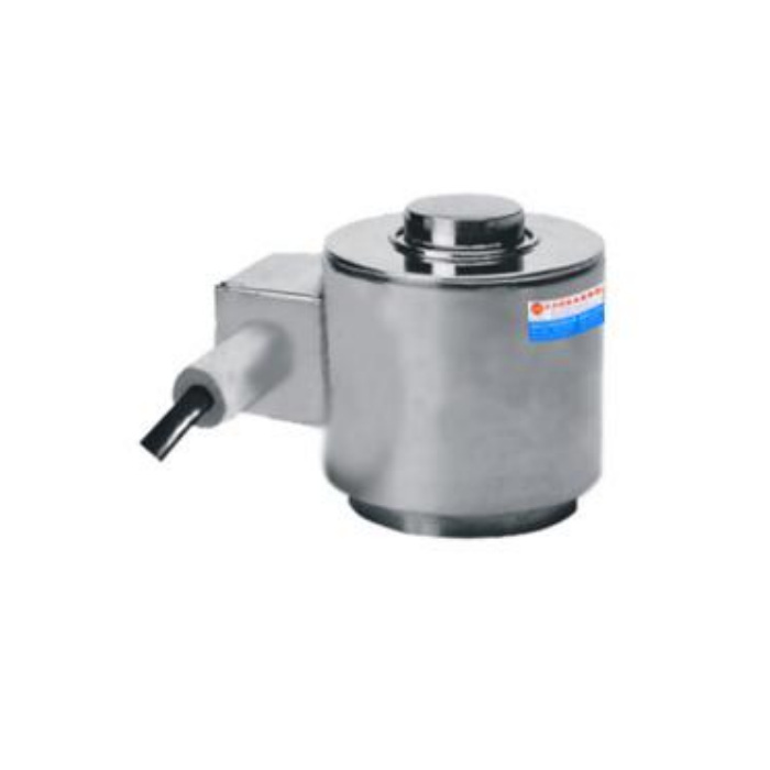

METRAVON MV-LC0028 is a compression column load cell with a curved upper contact and a central threaded base feature. Its rated outline changes substantially within the 20-60 t interval. A replacement should therefore be checked at the upper seat and lower base together: matching the external diameter or the base screw alone does not establish the same contact profile, installed height or support reaction.
Match the compression column load cell top profile to the retained seat
In the 20 t row, the upper contact G is 31.8 mm and the curved-profile entry D is 150 mm. At 30 t G changes to 38 mm while D remains 150 mm. The 40/50 t group has G = 54 mm and D = 200 mm; the 60 t row uses G = 79 mm and D = 309 mm. D belongs to the SRD callout at the curved contact. It is not the overall sensor height. Retain an old upper seat only after the full contact section and permitted movement have been checked.
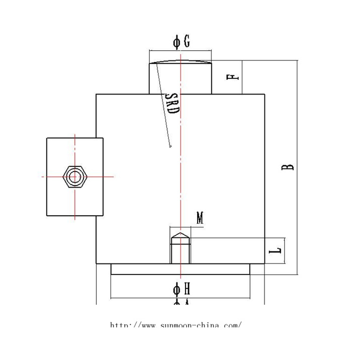
Review base thread, supporting land and height in one section
The 20 and 30 t rows specify M12, whereas 40, 50 and 60 t use M20. Other features change at the same time. For example, the 20 t body A and overall B references are 70 and 62.8 mm; at 60 t they are 166 and 144 mm. The lower H reference is a supporting-land diameter, not another thread size. Ask for the complete base contact, thread pitch and engagement detail. A central screw must not bottom out or become an unintended force path through a locally made adaptor.
| Item | Value | Selection notes |
|---|---|---|
| 20 t: A / B / G / M | 70 / 62.8 / 31.8 mm / M12 | D150 is the curved-contact reference, not overall height. |
| 30 t: A / B / G / M | 100 / 117 / 38 mm / M12 | The same base thread does not mean the same body or seat. |
| 40 / 50 t: A / B / G / M | 107 / 127 / 54 mm / M20 | Read the rated base land and contact section with these values. |
| 60 t: A / B / G / M | 166 / 144 / 79 mm / M20 | The upper curved-contact reference changes to D309. |
| Bridge input / output resistance | 400 +/-20 / 380 +/-5 ohms | Check the actual multi-support reader arrangement. |
| Precision / temperature effect | 0.05% FS / 0.02% FS per 10 deg C | Do not interpret these as an installed-system error guarantee. |
Check the physical support before replacing a drifting cell
With the structure safely supported, examine the contact surfaces, base condition, seat wear and clearance around the side enclosure. Do not try to correct a mechanical contact fault by changing the instrument span. Keep installation and removal access in the base design, particularly where a vessel leg prevents the sensor from being lifted straight out. Compression use is documented; a threaded recess is not evidence that this unit can be suspended from the base or used as an unrestricted tension link.
Recheck the weighing input after any mechanical change
The specified bridge has 2.0 +/-0.002 mV/V output, 400 +/-20 ohms input and 380 +/-5 ohms output resistance, with 10-12 V DC excitation. Use the terminal functions supplied with the actual sensor, not an assumed wire-colour polarity. If an existing indicator serves several supports, identify every connected bridge and any junction-box adjustment before accepting the replacement. Calibration then needs agreed force or weight references through the completed upper-seat and base arrangement, not only an empty zero adjustment.
Define the useful reading interval and exposure requirements
Precision is 0.05% FS and temperature effect is 0.02% FS per 10 deg C. State the tare, maximum local reaction and useful net increments so these full-scale entries can be assessed for the application. The operating temperature is -40 to +85 deg C. For IP68, specify the actual water conditions and termination location; confirm alloy steel or stainless steel separately. The sensor safe-load entry of 200% FS is not a rating for the retained seat, central fixing, vessel leg or a site proof-load procedure.
If the retained plate has paired base positions, compare the MV-LC0027 twin-fixing outline. The mounting decision needs its full height and upper contact, not only a comparison between M12, M16 and M20 thread labels.
Curvature labels, base-adaptor reuse and replacement tests
Q1. Does D150 mean the 20 t sensor is 150 mm high?
D identifies the curved-end profile through the SRD callout. Overall B for that metric row is 62.8 mm. Compare the complete outline and upper-seat section so a curvature value is not used as a support-height dimension.
Q2. Can an M12 base adaptor also be retained at 30 t?
Both 20 and 30 t rows show M12, but their body, overall height, upper contact and lower supporting land differ. Confirm thread engagement and both bearing interfaces before retaining the adaptor. The shared thread is only one part of the comparison.
Q3. Can the bottom thread be used as a suspension point?
The stated arrangement is for compression. No suspension or tensile rating is established by the threaded recess. Request an approved alternative or a confirmed assembly design if the project requires tension or lift-off restraint.
Q4. What should be tested after replacing a sensor under an existing leg?
Check mechanical clearance and repeat loaded readings through the final seat, then record unloading return and the relevant support positions. Use a safe agreed load method. A corrected empty reading does not establish that the replacement carries the leg reaction properly.
