Chinese
 Spanish
 Russian
 Portuguese
 French
 German
 Indonesian
 Thai
 Vietnamese
 Arabic
 Italian
 Turkish
 Polish
 Japanese

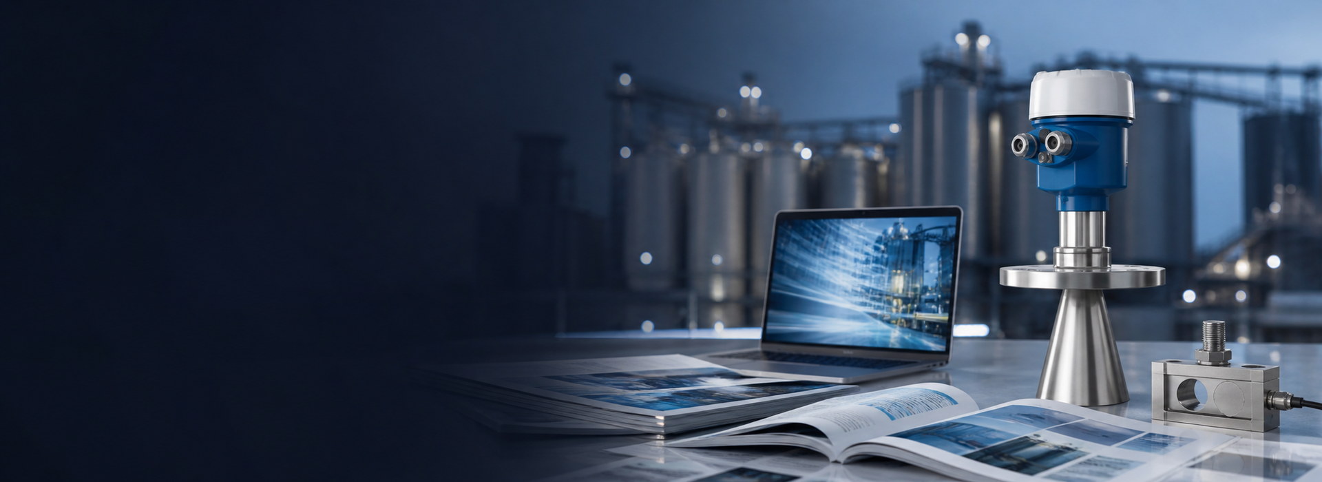
Urban waterlogging level monitoring relies on a fixed radar water level meter that reports water height against a local datum at a street inlet, underpass or dewatering well. The station must tolerate a short measurement dead zone, keep its beam fully on the water, and buffer samples when the network drops. Used well, it gives minutes of flood-warning lead time.
Defining the datum for a waterlogging point
A flood-warning reading is meaningless until the number is tied to a fixed, surveyable reference. Urban waterlogging level monitoring takes the well floor or a nearby kerb benchmark as zero, not an arbitrary sensor reading. The install height of the antenna above that datum must be recorded on the as-built drawing, because every later value is subtracted from it during data processing.
The datum rule that governs a 30 m reservoir span applies unchanged at 1.2 m scale in a 1.2 m diameter street well. Write the offset down before commissioning, not after a storm has already flooded the site. A datum that exists only inside the controller firmware is lost the moment that unit is replaced, which is the most common cause of a "new sensor reads differently" complaint.
Short-range dead zone and wellhead obstruction
The radar water level meter cannot trust a reading taken inside its near-antenna dead zone. For an 80 GHz unit this blind band is typically 0.4 m; a reading closer than that to the antenna is discarded or under-reported by the internal echo logic. In a narrow dewatering well the beam also spreads, so at a mounting height of 2.8 m an 8° beam covers a spot about 0.4 m across, which is fine for a 1.2 m diameter well but overshoots a 0.3 m bore.
Keep the antenna axis vertical and the entire beam footprint on the water surface at every expected level. A tilted mount of more than a few degrees throws the measurement point off the water and onto the opposite wall, producing a stable but false value. The beam must also clear any ladder rung, pump riser or reinforcement bar within 0.2 m of the intended spot.
Sampling density during a rainfall event
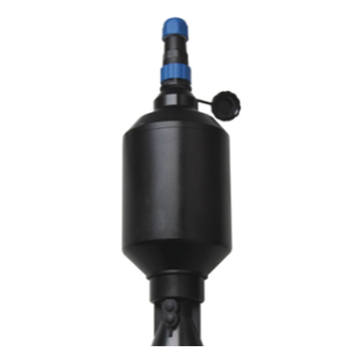
A storm does not raise water uniformly, so the reporting interval matters as much as the accuracy. Urban waterlogging level monitoring at a busy underpass should log at 1 min during active rain and relax to 5 min when dry, rather than holding one slow rate all day. The table below sets a defensible pattern by local condition so the controller rule is written down instead of left to an operator.
Solar-powered stations on 12 V or 24 V DC batteries must balance sample rate against energy draw. A 1 min burst for 30 min costs far less than continuous fast logging, and it captures the steep initial rise that decides your warning lead time. Set the threshold for "active rain" from a tipping-bucket input or a local rain sensor, not from a remote forecast that may lag the real cell over the site.
| Condition | Sampling interval | Telemetry mode | Power draw (typical) |
|---|---|---|---|
| Dry, no forecast rain | 5 min | LoRa / 4G idle | 0.6 W average |
| Active rainfall event | 1 min | 4G burst | 1.8 W average |
| Network outage | 1 min buffered | Store 7 days | 1.8 W average |
| Post-event recession | 5 min | 4G idle | 0.6 W average |
These are typical engineering ranges; confirm the figures against the current datasheet and the site battery capacity before fixing the interval.
The rise-rate calculation that sets a defensible alarm
The point of urban waterlogging level monitoring is lead time, and lead time comes from a rise rate, not a single level. The worked example below is illustrative, based on assumed site values, and is not METRAVON measured data. It shows how an alarm level and a mount height combine into minutes of warning.
Assumed site values:
- Antenna height above well floor, H_a = 2.80 m
- Near-antenna dead zone, d_min = 0.40 m
- Observed rise during first minutes of a storm, r = 15 mm/min
- Alarm level set 0.50 m below the well rim, i.e. level_a = 1.20 m
Calculation:
- Valid measurement band = H_a − d_min = 2.40 m, so any level up to 2.40 m is trustworthy.
- Time from an assumed zero starting level to alarm = level_a ÷ r = 1.20 m ÷ 0.015 m/min = 80 min. At the same assumed constant rise rate, the remaining 0.50 m from alarm to rim represents about 33.3 min; real storm rise rates can change.
- Boundary: if a reading lands above 2.40 m, the meter holds its last valid value or flags echo loss — a stuck sample must be flagged, not trusted.
When a fixed radar station will fail you
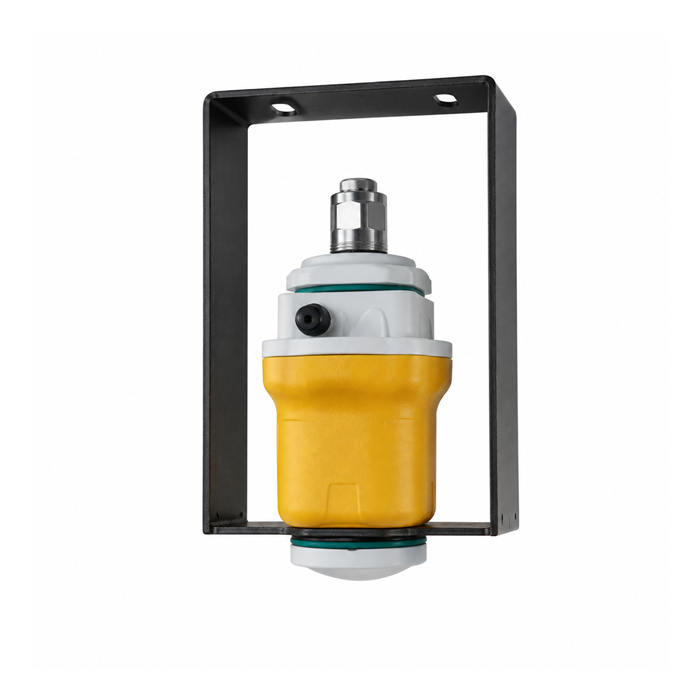
There are conditions where urban waterlogging level monitoring with a fixed radar water level meter should not be specified, or at least must be backed up by a second method. If the water surface is broken by violent aeration from a dewatering pump, the radar sees a rough, partially reflective interface and the returned echo weakens below the trigger level. A foam or heavy oil film thicker than a few millimetres likewise scatters the beam before it reaches the water.
In a well so narrow that the beam footprint exceeds the water width, the radar reads the opposite wall and reports a stable but wrong distance that no amount of averaging will fix. Freezing condensation inside the antenna housing during clear-night radiation also degrades the near-field signal, especially where the air temperature swings 25 °C between afternoon and dawn. Treat any of these as a failure of the method, not just of the unit, and document the backup rule in the site plan.
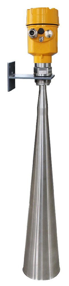
A point acceptance table for the site handover
Before the station is signed off, record the items below so a different technician can verify the installation later. Urban waterlogging level monitoring only stays reliable if the datum, dead zone and telemetry are documented together, because the next person to service the site will not have been at the install. The table is the minimum handover set, not a full commissioning report.
| Acceptance item | Required evidence | Pass condition |
|---|---|---|
| Datum offset | As-built sketch, mm | ±10 mm to survey mark |
| Dead-zone clearance | Beam check at low water | Highest expected level ≤ 2.40 m (at least 0.40 m below the antenna) |
| Beam on water | Photo of footprint | Beam footprint fully on water |
| Telemetry buffer | Log during outage | ≥ 7 days stored |
| Solar supply | Voltage under load | ≥ 11.5 V DC at dusk |
Mark temporary commissioning readings separately from permanent acceptance; a value taken during a single storm is not proof of long-term performance, and mixing the two tiers causes disputes at handover.
FAQ
Q1. What is the minimum measuring range I should plan for in a street well?
The direct answer is to plan for the full possible water depth from the datum to the rim, not just the normal standing water. In an underpass the usable span may reach 1.5–2.0 m during a 1-in-10-year event, so size the antenna height to keep that level inside the valid band. Confirm the exact figure against the local drainage design and the meter's dead zone before ordering the bracket.
Q2. How often should the station sample during a storm?
The direct answer is to switch to 1 min logging when rain starts and return to 5 min when it stops. A faster rate captures the steep initial rise that sets your warning lead time, while a constant fast rate wastes battery on a solar site. Keep the changeover rule in the controller, and trigger it from a local rain sensor rather than a delayed remote forecast.
Q3. Why does my radar read a steady level even when water is rising?
One possible cause is that the surface has entered the near-antenna dead zone; check distance and diagnostic status before assigning the cause. At an antenna height of 2.8 m and a 0.4 m blind band, any level above 2.4 m is untrustworthy: the meter holds its last valid value or flags echo loss — a stuck sample must be flagged, not trusted. If inadequate clearance is confirmed, raise the antenna or select a documented arrangement with a suitable near-range limit. Changing the datum only renumbers the level; it does not increase the physical antenna-to-water distance. Re-verify the reference and usable range after any mounting change.
Q4. Can a narrow dewatering well use the same radar as an open reservoir?
The direct answer is only if the beam footprint at the water surface stays smaller than the well diameter. An 80 GHz unit with an 8° beam at 2.8 m height covers roughly 0.4 m, which suits a 1.2 m well but fails a 0.3 m bore. Measure the bore before ordering, and prefer a stilling tube in very narrow shafts to keep the beam on water.
Q5. What happens to the data when the network drops?
The direct answer is that a properly specified station buffers samples locally for at least 7 days and forwards them in order when the link returns. Without buffering, a storm that knocks out the 4G mast also erases the very data you need for warning. Confirm the buffer depth and time order during commissioning, and test it with a real, timed outage rather than a paper check.
Q6. Do I need a fixed power supply or is solar enough?
The direct answer is that solar with a 12 V or 24 V DC battery is enough for most urban and remote wells if the sample rate is managed. A 1.8 W average draw during storms and 0.6 W at rest fits a modest panel and battery. Size the array from the worst-month sunlight and the buffered-log requirement, then test the voltage under load at dusk.
SUMMARY
Urban waterlogging level monitoring gives useful flood warning only when the reading is tied to a local datum, kept outside the 0.4 m near-antenna dead zone, and sampled fast enough to catch a 15 mm/min rise. A defensible next step is to survey the well floor, record the antenna offset on the as-built sketch, and calculate time-to-alarm and the remaining alarm-to-rim warning time separately. In this constant-rate example they are 80 min from a zero starting level and about 33.3 min after the alarm, respectively.
Talk to a METRAVON engineer about this application
If you are specifying a monitoring point, send us the well or inlet dimensions, the expected maximum water depth, and the available power source. Our engineers will check the antenna height against the dead zone and suggest a sampling plan that fits your battery and network.