Chinese
 Spanish
 Russian
 Portuguese
 French
 German
 Indonesian
 Thai
 Vietnamese
 Arabic
 Italian
 Turkish
 Polish
 Japanese


In a small batch vessel the fill rate sets how fast the level transmitter must update. A radar level transmitter for small batch tanks is specified by response time, damping and usable span. On a 1.5 m vessel a 400 L batch added in 40 s can hide 25 mm of level behind a 2 s damping setting.
Set the update time for a radar level transmitter for small batch tanks
Batch vessels change level quickly because a large fraction of the working volume arrives in a short time. Sugar dissolving tanks, alkaline electrolysers, additive tanks and filling machines commonly add 20 % to 50 % of their span in under a minute. The transmitter must deliver a fresh value faster than the level moves, or the control loop closes on an old number.
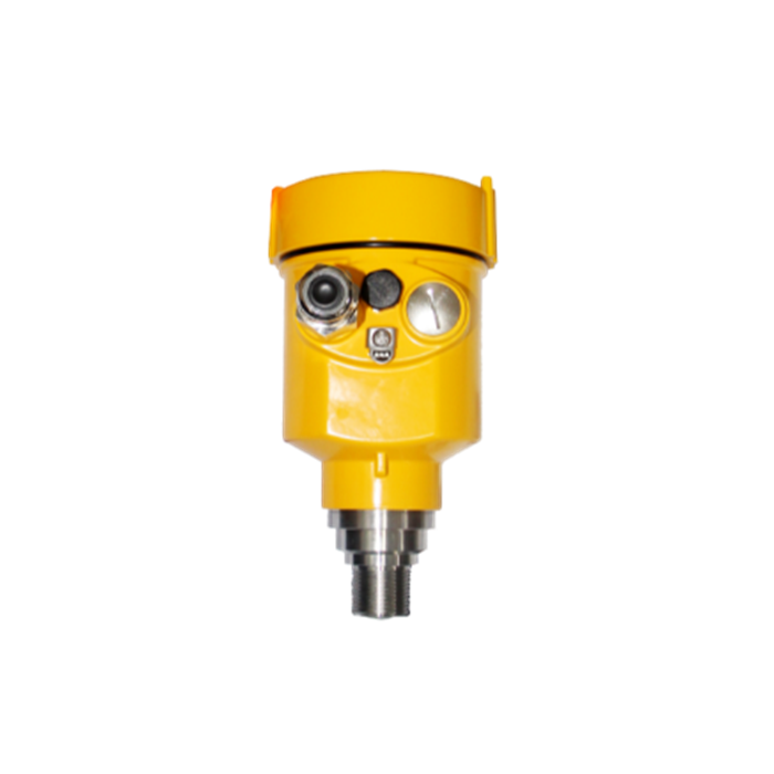
Start from the maximum fill rate, not the average. Convert the volumetric inflow into a rise rate using the free surface area, decide how much lag the batch can tolerate, and divide the tolerance by the rise rate to get the largest acceptable update interval. A radar level transmitter for small batch tanks is then selected by that interval and by the damping constant, which acts as an additional filter. Datasheet accuracy, often quoted as ±2 mm under static conditions, says nothing about behaviour during a ramp; a 4-20 mA output with a slow update can still be wrong by tens of millimetres while the tank fills. Check the update time and damping range on the current product page before ordering.
Convert volume flow into a rise rate
Worked example based on assumed site values (illustrative calculation, not field-measured data). A vessel of height H = 1.5 m has a free surface area A = 0.80 m². A batch of 400 L is added in 40 s, so the volume flow is Q = 0.400 m³ / 40 s = 0.010 m³/s, or 10 L/s. Dividing by the area gives a rise rate v = Q / A = 0.010 / 0.80 = 0.0125 m/s, or 12.5 mm/s. Over the 40 s fill the level rises 0.500 m, one third of the vessel height.
The boundary condition is that A must be the free surface at the working level, not the geometric cross-section of an empty tank: an internal coil, a mixer shaft or a baffle reduces the effective area and raises the rise rate. Where the vessel is conical or horizontal, A changes with level and the conversion has to be evaluated at the fastest point in the batch. A rise rate taken at the wrong elevation understates the required update speed for a radar level transmitter for small batch tanks.
Check damping against the batch tolerance
Damping is a first-order filter with time constant τ. For a steadily rising level the indicated value lags the true level by approximately τ*v once the ramp has settled. If the batch tolerance is 10 mm, the largest usable time constant is τ ≤ 0.010 m / 0.0125 m/s = 0.8 s. A default setting of τ = 2 s produces a lag of 2 * 12.5 mm/s = 25 mm, which is 5.0 % of the 0.500 m batch rise and 20 L of extra liquid on a 0.80 m² surface. The cutoff based on the indicated level therefore arrives late.
| Fill case | Rise rate (mm/s, at A = 0.80 m²) | τ = 2 s lag (mm) | τ needed for 10 mm lag (s) | Batch verdict |
|---|---|---|---|---|
| 200 L in 40 s | 6.25 | 12.5 | 1.6 | Fails (25 % over tolerance) |
| 400 L in 40 s | 12.5 | 25.0 | 0.8 | Fails at 2 s |
| 400 L in 20 s | 25.0 | 50.0 | 0.4 | Fails at 2 s |
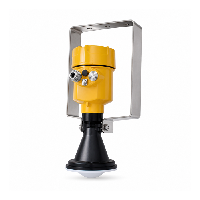
These are calculated values for the assumed vessel, not product specifications. Confirm the available damping range, the update time and the response of the 4-20 mA output on the current data sheet, and verify the final setting with a real fill rather than a simulated ramp.
A radar level transmitter for small batch tanks should not be run with heavy damping when the batch lasts only a few time constants — a time constant of 1 s or more on a 40 s batch is already too slow. In that regime the reading never catches up before the inlet closes, and the apparent stability of the signal is a filter artefact. Reduce τ first; only then consider surface turbulence or a stilling arrangement.
Compute the dead-zone fraction of the span
On a short span the near-field dead zone is a large share of the measurement. Combine it with the foam layer and the bottom exclusion into one figure: f = (d_block + d_foam + d_bottom) / H. For the assumed vessel, d_block = 0.30 m, representing a 0.20 m extended nozzle on this tank; a flush 80 GHz lens antenna would be nearer 0.10 m, to be verified on the current data sheet. With d_foam = 0.10 m and d_bottom = 0.05 m the total is 0.45 m and f = 0.45 / 1.5 = 0.30, or 30 %. The usable span is 1.05 m. At 0.10 m the total dead zone falls to 0.25 m, the dead-zone fraction to 17 %, and usable span rises to 1.25 m.
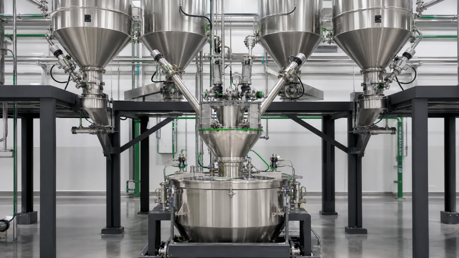
Set an acceptance limit before selecting the antenna. If the target is f ≤ 0.25, the total dead zone must be ≤ 0.375 m; with the same foam and bottom allowances, the blocking distance has to be ≤ 0.225 m. A nozzle that adds 0.20 m to the antenna position can fail the check even though the transmitter itself is unchanged. The options are a shorter nozzle, a flush-mounted antenna with a smaller blocking distance, or a raised mounting that keeps the sensor face clear of the highest level. Recompute f after any adapter or insulation change, and confirm the foam allowance from a real batch.
Allow for foam, condensation and boiling
Batch conditions change the usable span independently of the fill rate. Vacuum lowers the boiling point, so a liquid calm at atmospheric pressure can expand into foam and droplets when the vessel is evacuated; a 1 m liquid column may become a much taller aerated layer. Agitation adds a moving surface, and a guided wave probe should not be used where a mixer can strike or bend it. Alkaline electrolysers run at 80 °C to 100 °C, which sets the seal and housing requirement rather than the fill rate. Condensation and crystallisation on the antenna cause a separate failure: a product such as benzene crystallises below about 6 °C, and vapour condensing on a cold nozzle can coat the antenna and weaken the echo.
These effects should be listed against the batch cycle rather than handled with one generic setting. Where foam is persistent, specify the surface to be measured and, if necessary, a stilling well; where the product condenses or crystallises, confirm that the offered antenna, seal and any heating or purge provision suit the minimum nozzle temperature. A technical article on batch-tank trials covers separating a temporary test result from permanent acceptance. Radar measurements are unaffected by air temperature and humidity, but not by a layer of liquid on the antenna.
Record the acceptance numbers at handover
The checks above are only useful if written down. At handover, record the vessel height and free surface area, the maximum batch volume and fill time, the measured rise rate, the configured update time and damping constant, the blocking distance with the installed nozzle, the foam allowance, the computed dead-zone fraction and the high-high trip elevation. Then run one real fill with the final settings and log the indicated level against a reference at the start, the middle and the cutoff.
- Confirm the 4-20 mA scaling and the datum after any change to damping or range.
- Verify the reading recovers correctly after a power interruption.
- Check that a simulated stale value is flagged rather than held as a valid level.
- Keep the configuration record so a replacement unit can be set up without guessing.
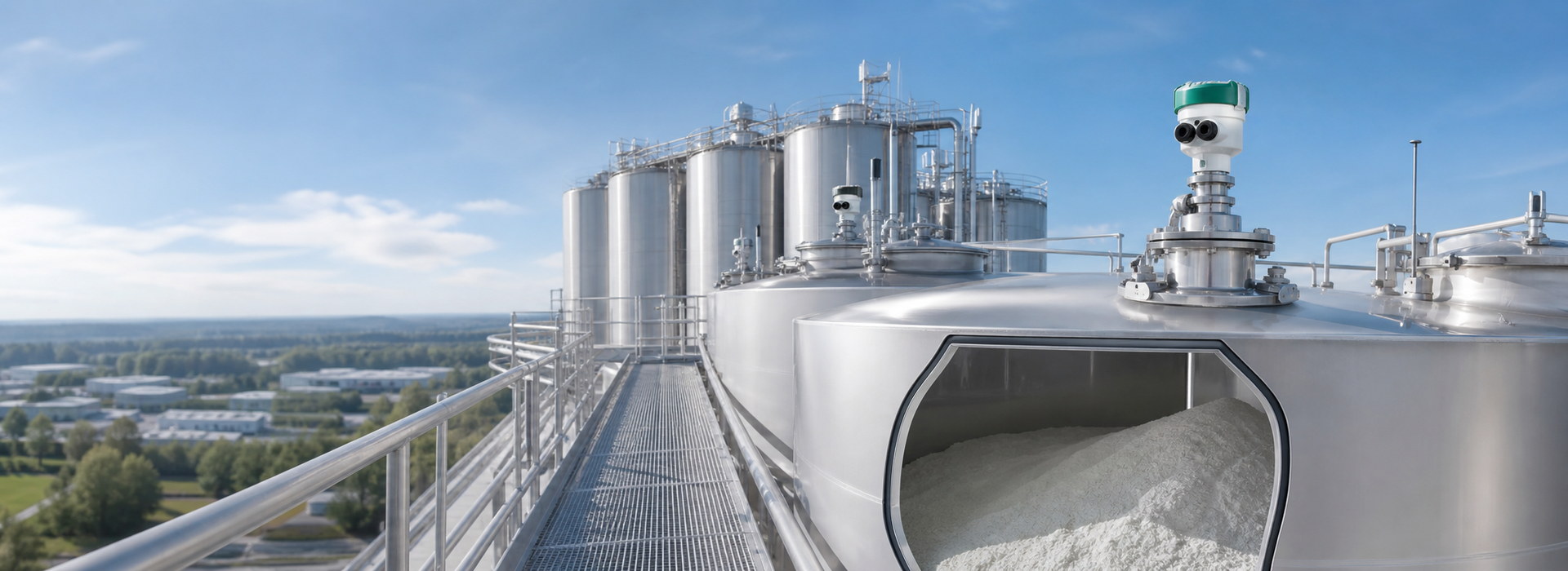
A radar level transmitter for small batch tanks is accepted on response and usable span, not on a static accuracy figure.
FAQ
Q1. What sets the response requirement for a radar level transmitter for small batch tanks?
The maximum fill rate divided by the free surface area. In the worked 1.5 m vessel, 400 L in 40 s gives 12.5 mm/s, so a 10 mm tracking tolerance needs both an update interval and a damping time constant of 0.8 s or less. Static accuracy such as ±2 mm does not describe behaviour during a ramp.
Q2. Why does a stable reading sometimes hide a rising level?
Because damping filters the output. With a 2 s time constant and a 12.5 mm/s rise, the indicated level lags by 25 mm, which is 5 % of the 0.500 m batch rise. The signal looks calm while the tank keeps filling, so a cutoff based on it arrives late. Reduce the damping constant first.
Q3. How large a dead-zone fraction is acceptable on a 1.5 m vessel?
Set the limit from the batch, but 25 % is a practical ceiling. In the worked example a 0.30 m blocking distance, 0.10 m of foam and a 0.05 m bottom allowance give 0.45 m, or 30 % of span, which fails. To reach 25 % the blocking distance must fall to 0.225 m or less.
Q4. Does foam reduce the accuracy of the distance measurement?
Not usually; it reduces the usable span. A persistent 0.10 m foam layer must be added to the dead-zone allowance, and a thick or collapsing layer can move the echo source between the foam surface and the liquid beneath. Define which surface the batch needs, then confirm the allowance from a real fill.
Q5. Should a guided wave probe be used in an agitated batch vessel?
No, not where a mixer can strike or bend it. Agitated service usually calls for a non-contact horn or lens antenna, with false-echo handling for the blades. Vacuum boiling and condensation also need attention: confirm the antenna, seal and any heating or purge provision against the minimum nozzle temperature.
Q6. What belongs in the handover record?
The vessel geometry, maximum batch volume and fill time, measured rise rate, configured update time and damping constant, blocking distance with the installed nozzle, foam allowance, dead-zone fraction and trip elevation. Add a real-fill test with reference readings at the start, middle and cutoff, plus the 4-20 mA scaling check.
SUMMARY
A radar level transmitter for small batch tanks has to be chosen on timing and usable span: in the worked 1.5 m vessel a 12.5 mm/s rise needs an update interval of 0.8 s or less to hold a 10 mm tolerance, a 2 s damping constant hides 25 mm of real level, and a 0.45 m dead zone consumes 30 % of the span. The next step is to compute the dead-zone fraction from the installed nozzle and measured foam, then run one real fill with the final settings.
Talk to a METRAVON engineer about this application
Let us know the vessel height, the batch volume and fill time, the foam or vapor layer, the nozzle and blocking distance, and the control tolerance you need. Our engineers will check the update time, damping constant and usable span against your batch cycle and the installed nozzle before suggesting a configuration.