


 Chinese
 Spanish
 Russian
 Portuguese
 French
 German
 Indonesian
 Thai
 Vietnamese
 Arabic
 Italian
 Turkish
 Polish
 Japanese


Remote Industrial Tank Level Monitoring: Sensors, RTUs, Alarms and Offline Data Integrity
Industrial tanks, distributed pump stations, remote basins and hydrological sites require more than a local level reading. Data must reach an operations room or platform for trending, low-level alerts, overflow warnings and service planning. Long-term reliability depends on the entire chain—sensing, acquisition, connectivity, timestamps and alarms—not merely a sensor labeled IoT-ready.
Define the measured variable, alarm purpose and outage behavior before selecting the level sensor, 4-20 mA or RS485 interface, RTU and communication network. Offline buffering, retention through power loss and eventual backfill must be specified and tested separately.
Divide Responsibilities Across the System
| Component | Main Function | Boundary to Verify |
|---|---|---|
| Level sensor | Measures distance, level or pressure | Datum, usable range, accuracy, fault status |
| RTU/logger | Samples, scales, timestamps and stores | Input types, storage and outage behavior |
| Network | Delivers data to server | Coverage, SIM/antenna, reconnect policy |
| SCADA/cloud | Displays, trends and alerts | Freshness, units, alarms, history |
An RS485 output does not mean the sensor includes 4G, GPS, cloud integration or historical storage. The RFQ should assign each function to a defined component.
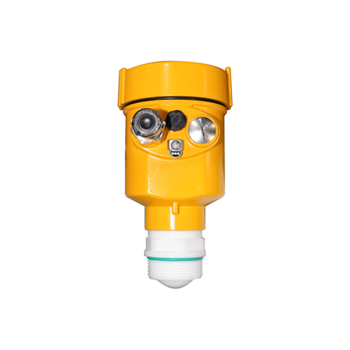
Configure 4-20 mA and RS485/Modbus Correctly
4-20 mA suits conventional PLC analog-input channels but requires checking two-/four-wire arrangements, supply voltage, loop load, span direction and fault-current interpretation. RS485/Modbus RTU suits polling digital instruments and shared buses, provided addressing, baud rate, parity, register data type, scaling and wiring are defined.
For example, if a tank transmitter maps 0–6m level to 4-20 mA, the receiving controller can calculate H=(I−4)/16×6. At 12mA, the mapped level is 3m. This only applies to that positive level span, not distance output or reversed mapping.
For multiple Modbus devices, retain a tag list with unique slave addresses, register locations, numeric types, byte order and units. Termination and bias arrangements should match the actual bus topology and equipment requirements.
Distinguish Low Level, High Level and Device Failure
Low liquid level is not sensor failure; communication loss is not a zero-level reading. The platform must distinguish valid process readings, low/high alarms, communication timeout and sensor diagnostic conditions.
To avoid repeated alerts around a threshold, use hysteresis and delay where approved. As an illustrative control rule, a high-level alarm might activate at 4.5m and clear only below 4.3m; real thresholds require process-owner approval.
For fire-water systems, hazardous-chemical overfill, pump protection and safety instrumented functions, ordinary cloud alerts do not replace approved independent safety controls.
Network Outage, Power Loss and Backfill Are Different
Network outage: if the RTU remains powered and has local storage, it may continue to record samples. After reconnection, it may be able to send the stored records with original timestamps, subject to model support and retention capacity.
Power loss: without backup power, new measurements generally stop. Retaining previously stored data depends on nonvolatile memory and the implementation of write and recovery behavior.
Backfill should preserve source measurement time and device identity, using sequence numbers or unique record keys to prevent duplicate records. Servers must display receipt time and data freshness separately; yesterday's delayed record must not appear as the latest live level.
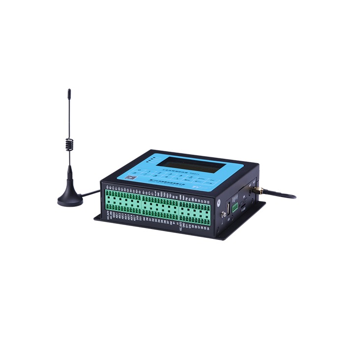
Select Communications and Power for the Actual Site
| Site | Common Approach | Main Risk |
|---|---|---|
| Plant tanks | Existing PLC/DCS and Ethernet | Scaling and industrial network boundaries |
| Remote basins | Solar, battery and cellular RTU | Peak modem load and autonomy |
| Multi-point pump station | RS485 bus polling | Address conflicts and wiring |
| River station | Low-duty sampling with adaptive reporting | Time integrity, gaps and flood-season power |
Solar sizing must include modem transmit and reconnect peaks, sampling duty cycle, reserve days, usable battery capacity and charger efficiency—not just sensor nameplate consumption.
Why Can the Local Reading Be Correct but the Cloud Level Wrong?
Common causes include confusion between distance and level, inconsistent engineering units, reversed 4-20 mA mapping, wrong Modbus byte order, incorrect register scaling or a mismatched installation datum.
A proper loop-test record contains five points: independent field level; transmitter display; actual mA or raw Modbus register; RTU scaled value; and final server value with source timestamp. The whole chain—not a single screen—must pass acceptance.
Two-Site Example: Tank and Pump Station
Consider a process tank with a 4-20 mA level transmitter and local low-level alarm, and a remote pump station using an RS485/Modbus sensor. Compatible RTUs can acquire each signal and send it to one dashboard, but the stations require separate I/O definitions and alarm rules.
The tank must preserve correct level scaling, hysteresis and fault behavior. The pump station requires verified Modbus addressing/registers and clear responsibilities for pump controls. Both sites need source timestamps and link-status monitoring so that an offline station is not mistaken for an unchanging level.
Test Plan from Pilot to Handover
- Confirm sensor range, datum, medium and installation
- Verify valid, low/high and failed signal conditions
- Compare RTU units, types and scaling with the receiving system
- Test buffering, backfill and deduplication after a network outage
- Verify parameter retention and data gaps after a restart
- Check alarm hysteresis, stale-data indication and notification permissions
- Archive wiring, tag/I/O schedule, register map and test evidence
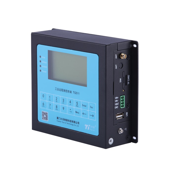
Information Needed for a Project RFQ
Provide site count, devices per site, medium and range, available 4-20 mA/RS485 instruments, PLC/RTU models, power, network coverage, alarm logic, upload interval, tolerated outage, retention target and any MQTT/HTTP/cloud requirements. Buffering, TLS, GPS and protocol support are model- and configuration-dependent.
FAQ
Q1. Can an RS485 sensor upload directly to the cloud?
The RS485 electrical interface does not by itself provide cellular networking or a cloud protocol. A compatible RTU or gateway is normally needed unless those functions are documented in the sensor. Confirm the serial protocol, register map and server interface separately before assigning the acquisition and transmission responsibilities.
Q2. Does data automatically upload after the network returns?
Only if the selected logger and server support the required storage and replay behavior. Test an outage with original timestamps, a controlled restart and reconnection. Check missing records, duplicates and whether late historical data are marked as historical rather than appearing as the latest live level.
Q3. Can one RTU handle both 4-20 mA and RS485?
Some configurations support both, but verify channel count, input isolation, sensor power, serial capacity and the required protocol on the ordered model. Test valid values and fault conditions through to the final display. A list of available interfaces does not establish that every combination can operate together at the required rate.
Request a Multi-Site Monitoring Configuration and Quote
Share the instrument list, site count, ranges, installed signal interfaces, power, network, alarm and storage requirements. METRAVON can help evaluate sensing and RTU acquisition options against verified model capabilities.
METRAVON Radar Level Products | Send an inquiry | Arvin@metravon.com
