


 Chinese
 Spanish
 Russian
 Portuguese
 French
 German
 Indonesian
 Thai
 Vietnamese
 Arabic
 Italian
 Turkish
 Polish
 Japanese


Real-Time River Level Monitoring System Design: Sensors, 4G Telemetry, Alarms and Solar Power
A real-time river level monitoring system combines sensing, data acquisition, communications, power and supervision. Its job is not simply to display a remote number: each reading needs a known datum, timestamp and quality status so that operators can use it for flood surveillance and water-resource decisions.
At bridges, remote rivers, irrigation channels and urban drainage sites, the design must cover minimum and maximum water level, mobile coverage, days without sunshine, alarm latency and safe maintenance access. A one-minute sampling interval does not guarantee an alarm will arrive within one minute.
System architecture and data path
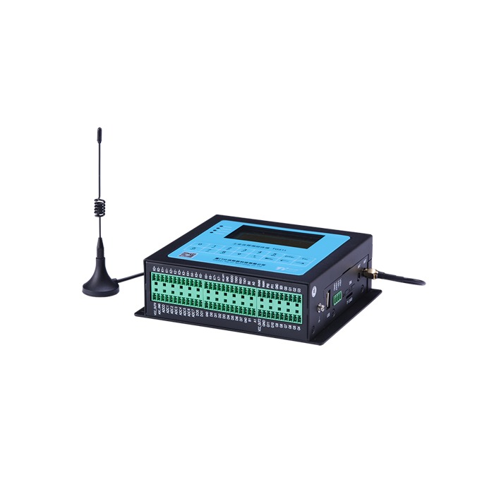
A complete station normally includes a sensor, data acquisition RTU, communications link, power subsystem, mounting hardware and monitoring application. A standard RS-485 sensor does not inherently supply cellular connectivity, cloud storage or SMS alerts.
| Element | Responsibility and selection issue |
|---|---|
| Level sensor | Distance or level value; document datum, operating span and interface |
| RTU/logger | Sampling, timestamps, quality flags, buffering and forwarding—verify by model |
| Communications | 4G, wired or other links; prove coverage, local bands and antenna location |
| Platform | Trends, stale-data indicators, threshold and device-fault alarms |
| Field installation | Bracket, enclosure, surge protection, power and maintenance access |
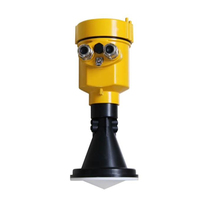
Compare METRAVON radar water level meters and data acquisition RTUs for interface compatibility.
Choosing radar, ultrasonic or hydrostatic sensors
| Technology | Where to consider it | Key risks |
|---|---|---|
| Radar | Non-contact bridge/bank installation; less underwater servicing | Beam overlap with bank or pier, exposed bed at low stage |
| Ultrasonic | Open channels with reasonably stable gas conditions | Sound-speed temperature correction, obstacles, near zone and condensation |
| Submersible hydrostatic | Wells and locations without a suitable overhead path | Silt, impact, vent tube, datum and water density |
Decide whether the required quantity is stage elevation, stage above a local zero or water depth; these are not interchangeable. River discharge does not follow automatically from a level reading.
Specify sampling, reporting and alarm latency separately
Write separate requirements for sensing interval, upload interval, event-alarm maximum delay and loss-of-communications alerts. A 60-second sampling and five-minute bulk upload schedule is merely an example; whether it meets flood-response needs is a project decision.
- Apply alarm thresholds to the approved stage datum, not directly to sensor standoff distance.
- Use justified hysteresis or persistence checks without concealing rapidly rising water.
- Show last valid timestamp and mark delayed readings as stale.
- Distinguish lost echoes, power loss, RTU outages and genuine high-stage events.
R = (H₂ − H₁) / Δt
If stage rises from 2.10 m to 2.40 m in 30 minutes, the average rise rate is 0.60 m/h.
This descriptive rate alone cannot forecast flood-peak arrival.
Solar power and offline data integrity
Size solar power from the sensor, RTU and modem energy demand in sleep, sensing and transmission states. Incorporate local solar yield, consecutive low-sun days, charging losses and usable battery capacity; sensor nameplate power alone is not enough.
E_day = Σ(P_i × t_i)
E_day is total daily energy in Wh, calculated across actual operating states.
Allow for ageing, cold weather and worst-season conditions.
During a network outage, original-timestamp records can only be retained if the station stays powered and the RTU has suitable storage. Acceptance tests should cover capacity, restart persistence, deduplication on replay and outage alerts.
River station commissioning and maintenance
- Survey sensor reference elevation, local zero and staff-gauge reference.
- Record local distance/stage and verify the platform engineering unit.
- Check near-zone clearance at flood stage and beam footprint at low stage.
- Interrupt communications, restore service and verify timestamps, backfill and deduplication.
- Exercise approved alarm conditions and measure actual delivery latency.
- Inspect power margin, earthing, surge protection, mounting strength and enclosure seals.
Before the wet season, after major floods and during planned inspections, check for shifted mounts, antenna fouling and unreasonable data jumps. One correct reading is not evidence of long-term reliability.
FAQ for project procurement
Q1. Does the level sensor itself provide 4G?
Only if cellular communication is included in that specific model. Otherwise an RTU or gateway must read the sensor and transmit the data. Confirm sensor protocol, local cellular bands, SIM arrangements and the receiving platform interface before ordering the station.
Q2. Does every communications outage destroy data?
Not if a powered logger retains the readings locally. Specify storage capacity and behavior after a power cycle, then disconnect the network during acceptance. On reconnection, check original timestamps, missing records and duplicates rather than checking only that the dashboard is online again.
Q3. Does a level sensor calculate river discharge?
A stage reading alone is insufficient. Discharge requires a valid site-specific stage-discharge relation or a suitable velocity and cross-section method. If discharge is part of the contract, specify the supporting measurements and validation separately from the level sensor.
Q4. Can remote alarms replace flood-response procedures?
No. They provide information for response, not flood prevention. Test threshold detection, transmission delay, stale-data warnings and the recipient escalation process. A received alert must still lead to an agreed operational action, with separate procedures for sensor or communications failure.
From a threshold to an actionable alarm
“Send an alert when level exceeds X” is not a complete flood-alert specification. Define the stage datum, persistence rule, clear threshold, recipients, whether logging continues offline and whether alerts require acknowledgement. Flashy mountain catchments may not tolerate a long smoothing window.
| Test event | Expected system behaviour |
|---|---|
| True threshold crossing | Record station, source timestamp, actual stage and threshold; notify approved recipients |
| Short noisy spike | Apply documented persistence/hysteresis without nuisance alarm storms |
| Sensor loses target | Flag a measurement-quality fault; do not silently report zero stage |
| Communication fails | Mark station offline/stale; log locally if supported |
| Network returns | Replay original timestamps while avoiding duplicates and repeated alerts |
Telemetry supports risk decisions but does not replace flood standards, forecasting models or human emergency management.
Request engineering selection and quotation from METRAVON
Send the number of stations, river width and mounting photos, highest/lowest levels, sampling/upload/alarm targets, power availability, local cellular bands and server protocol. We can assess suitable radar sensors, RTUs and accessories subject to actual model specifications.
Engineering email: Arvin@metravon.com
Phone / WhatsApp / WeChat: +86 153 6781 2163
