


 Chinese
 Spanish
 Russian
 Portuguese
 French
 German
 Indonesian
 Thai
 Vietnamese
 Arabic
 Italian
 Turkish
 Polish
 Japanese


Radar vs Ultrasonic Level Transmitter: Which Survives Your Tank
Both instruments measure distance using a returning signal, but ultrasonic depends on the acoustic conditions along the gas path. Radar uses electromagnetic waves and does not need a gas to propagate. Compare the actual models, operating atmosphere, surface and installation; neither a fixed price discount nor a frequency label establishes which instrument will work.
Two instruments, one measurement principle
An ultrasonic transmitter emits sound and evaluates its return from the surface. Many designs use the same transducer to transmit and receive, creating a near-end restriction. Frequency, blanking distance and operating limits are model-specific.
A radar transmitter uses electromagnetic signals; pulsed and FMCW designs process the return differently. A free-space antenna radiates into the vessel, while guided-wave radar uses a contacting transmission-line probe. The selected assembly and process conditions determine performance.
| Property | Ultrasonic | Radar |
|---|---|---|
| Carrier | Sound through the measuring atmosphere | Electromagnetic signal |
| Gas conditions | Sound speed and attenuation require assessment | Dense vapour and deposits can still matter |
| Vacuum | Requires a suitable acoustic medium and permitted pressure | Propagation needs no gas; assembly still needs a vacuum rating |
| Product surface | Check acoustic return, foam and turbulence | Check reflection, foam and target tracking |
| Accuracy and near zone | Use the exact model and reference conditions | Use the exact model and reference conditions |
| Cost | Obtain a current compliant quotation | Include installation and service scope |
Ultrasonic does not depend on the liquid dielectric constant in the same way as radar. However, suitable non-contact radars can also measure selected low-permittivity liquids. A static dielectric value alone does not establish that radar cannot measure a hydrocarbon or that ultrasonic is suitable for its gas and pressure conditions.
Why the speed of sound is the real specification
For an illustrative dry-air calculation over a limited temperature range, use v approximately equal to 331.3 + 0.606 T in metres per second, with T in degrees Celsius. The table assumes a true distance of 6.00 m and an instrument still using the 20-degree speed. It illustrates uncompensated distance error, not the performance of a modern compensated model.
| Air temperature | Speed of sound | Indicated distance for a true 6.00 m | Error |
|---|---|---|---|
| 0 °C | 331.3 m/s | 6.22 m | +0.22 m |
| 20 °C | 343.4 m/s | 6.00 m | 0 |
| 40 °C | 355.5 m/s | 5.80 m | −0.20 m |
| 60 °C | 367.7 m/s | 5.60 m | −0.40 m |
| 80 °C | 379.8 m/s | 5.42 m | −0.58 m |
Under those assumptions, the indicated distance at 80 degrees Celsius is about 0.58 m too short. If level is calculated as reference height minus distance, that distance error makes the indicated level too high. The calculation must not be presented as a universal field error.
Modern ultrasonic instruments may use integral or remote temperature sensing and other compensation. Verify where temperature is measured and whether it represents the acoustic path. Stratification or a changing gas mixture can leave a residual error even when a local temperature correction is active.
Radar propagation can also change with gas properties, especially in demanding dense-vapour or steam conditions. Use the selected instrument application data and any required compensation; do not infer a universal correction from optical refractive-index values or a single pressure threshold.
Gas composition, the error nobody checks
Gas composition changes acoustic velocity as well as temperature. Compare the actual process mixture with the compensation supported by the instrument, rather than assuming every nitrogen, carbon-dioxide or biogas atmosphere behaves like air.
For an assumed acoustic speed of 269 m/s and an instrument using 343 m/s, a true 6.00 m distance would be reported as about 7.65 m. With level calculated as reference height minus distance, the level would be too low, not too high. These assumed velocities illustrate the sign and scale of the calculation; actual gas data must be verified.
Blanketed reactors, digesters and solvent-recovery vessels therefore need a review of gas composition, pressure and temperature changes. A stable indication is not independent evidence that the configured propagation assumptions remain correct.
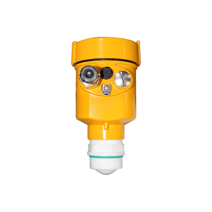
Where ultrasonic is the correct choice
Ultrasonic remains an option where its pressure, temperature, surface and acoustic-path requirements are met. Compare current quotations and installed maintenance evidence rather than assuming it is always cheaper or simpler.
- Clean water and wastewater sumps. Check the actual foam, turbulence, temperature gradient and access conditions. Both ultrasonic and radar may be suitable.
- Ambient chemical storage. Check chemical compatibility, vapour composition, pressure and the complete process envelope rather than accepting storage temperature alone.
- Open channel and flume measurement. The ultrasonic sensor measures water surface from above with no contact, and the flume gives it a stable, known geometry.
- Low-permittivity products. Ultrasonic does not require a dielectric threshold, but the acoustic atmosphere and process rating still matter. Compare purpose-suitable radar, guided-wave and other alternatives as well.
- Short spans and alarm duty. Check usable measuring zones and the required response and protection architecture. A small tank is not automatically inside every radar blocking distance.
Conditions to verify before selection
The service description should identify the conditions to include in the application review and acceptance test. None of the following conditions produces one universal pass/fail ranking across all models.
| Condition | Ultrasonic assessment | Radar assessment |
|---|---|---|
| Reduced pressure or vacuum | Acoustic propagation and permitted pressure | Full assembly pressure rating |
| Vapour or temperature gradient | Composition, compensation and path conditions | Gas effects, condensation and model limits |
| Foam or floating material | Intended reflecting surface and return quality | Intended surface, penetration and echo margin |
| Airborne dust | Attenuation during filling | Model, antenna and filling-condition performance |
| Deposits or condensation | Transducer condition and cleaning | Antenna/seal condition and approved cleaning |
| Moving surface | Representative target and response | Tracking, filtering and dynamic response |
A failure linked to filling should prompt checks for inlet interference, turbulence, foam, dust, power or configuration changes. The timing narrows the investigation but does not uniquely identify the cause.
Foam: the case that decides most projects
Foam structure, moisture, conductivity and thickness can change the return for either technology. Define whether the required quantity is liquid level below foam or the foam surface, then test the proposed instrument under representative conditions.
| Surface condition | What to define | Evidence required |
|---|---|---|
| Aerated surface | Liquid level or bubble/foam surface | Comparison during actual aeration |
| Persistent wet foam | Required boundary and expected thickness | Tracking through process changes |
| Dry or changing foam | Attenuation and loss-of-echo behaviour | Worst-condition signal and fault response |
| Crust, fat or debris | Which surface represents the process need | Independent observations and maintained access |
Do not select 26 GHz or 80 GHz from a universal foam chart. A working installation is useful evidence for that configuration and process, but any replacement still needs a documented application and acceptance review.
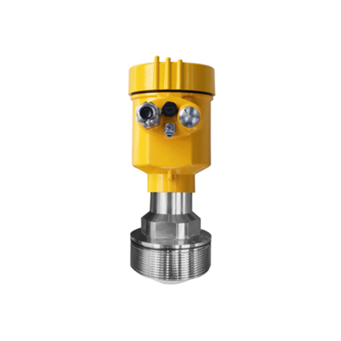
What it costs over five years
Compare lifecycle costs using site-specific equipment, installation, inspection, cleaning, required testing and outage assumptions. The relative costs and maintenance intervals are not fixed properties of the technologies.
| Cost element | Information needed for either option |
|---|---|
| Equipment | Current configuration-specific quotation |
| Installation | Mounting, power, cable and receiving-system changes |
| Maintenance | Observed deposit rate, approved method and access |
| Availability | Evidence from the required operating states |
| Lifetime comparison | Stated period, assumptions and sensitivity to downtime |
Neither option has a universal two-year cost crossover. Compare compliant installations and identify uncertain maintenance or outage assumptions before accepting a total-cost conclusion.
How to decide with what you already have
The decision needs four facts, and all four are already in the plant.
1. Does the tank operate within the proposed instrument pressure range, including any vacuum condition?
2. What gas, temperature gradient, steam, dust or condensate can affect the measuring path?
3. Is there foam on the surface at any point in the batch? Ask the operator, not the datasheet.
4. What do the failure and maintenance records show, and which causes have been established rather than assumed?
Keep an existing instrument when evidence shows it meets the required function. If a condition is outside its capability, compare suitable alternatives and state the acceptance test; radar is not an automatic cure for every difficult atmosphere or surface.
Frequently asked questions
Q1. Can an ultrasonic transmitter work in a vacuum?
Ultrasonic needs an acoustic medium and must remain within its permitted pressure conditions. Do not assign one minimum pressure to all models. Radar propagation needs no gas, but the complete assembly must be rated for the vacuum and process.
Q2. Is radar more accurate than ultrasonic?
Not universally. Compare actual specifications, installed uncertainty, reference conditions and required operating states. A well-suited ultrasonic installation can meet its duty, while an unsuitable radar installation can give an incorrect target.
Q3. Does a radar transmitter need a stilling well?
Not always. Either technology may use a suitably designed stilling arrangement where justified. Check geometry, hydraulic exchange, fouling and the selected model instructions rather than treating a pipe as a universal requirement or remedy.
Q4. Can ultrasonic measure solids in a silo?
Suitable ultrasonic and radar models can measure particular solids duties. Surface slope, dust, distance and the required level or volume result must be assessed. Frequency alone does not determine bulk-solids suitability.
Q5. Which one is cheaper?
Use current like-for-like quotations and site maintenance data. There is no reliable market-wide discount or fixed lifecycle crossover for every ultrasonic and radar installation.
Q6. Does a nitrogen blanket affect a radar transmitter?
It can, depending on pressure, temperature, composition and the instrument. Ordinary gas effects may be small, but demanding vapour conditions need model-specific assessment and any required compensation.
