


 Chinese
 Spanish
 Russian
 Portuguese
 French
 German
 Indonesian
 Thai
 Vietnamese
 Arabic
 Italian
 Turkish
 Polish
 Japanese


Radar Level Sensor for Viscous Liquids: Specify the Residue, Not Just the Viscosity
The useful distinction. A radar level sensor for viscous liquids does not fail because a viscosity number exceeds a single threshold. It fails because the product stays where it should drain, bridges an opening, crystallizes on a cooler surface or changes into foam. Two liquids at 5,000 cP can behave completely differently: one drains cleanly from an antenna, while the other forms a permanent insulating layer.
Replace “high viscosity” with a coating description
In the RFQ, describe what happens at the nozzle and probe after normal operation and after a shutdown. State whether the residue is wet, rubbery, hard, fibrous or crystalline; whether it builds continuously; and whether it can be removed by the normal cleaning cycle.
| Product behavior | Risk to the measurement | Design response to evaluate |
|---|---|---|
| Drains slowly but completely | Temporary coating and changing near echo | Suitable antenna, drainage orientation and diagnostics |
| Strings during emptying | Product remains suspended near the antenna | Location away from stream and non-contact configuration |
| Crystallizes on cooling | Hard layer and blocked nozzle or chamber | Temperature control and validated heat tracing |
| Cures or polymerizes | Permanent deposit requiring mechanical removal | Minimize wetted surfaces and define cleaning access |
| Contains fibers or solids | Bridging and probe loading | Mechanical clearance and non-contact option |
| Foams when agitated | Surface echo weakens independently of viscosity | Test real foam and agitation conditions |
Non-contact does not mean no product contact
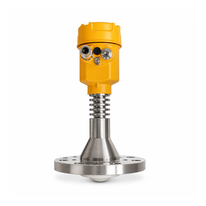
A non-contact antenna has no probe extending into the liquid, but vapor, splash and condensate can still reach it. Review the antenna face, process seal and nozzle as wetted or exposed components. Confirm chemical compatibility and the complete temperature cycle, including cleaning.
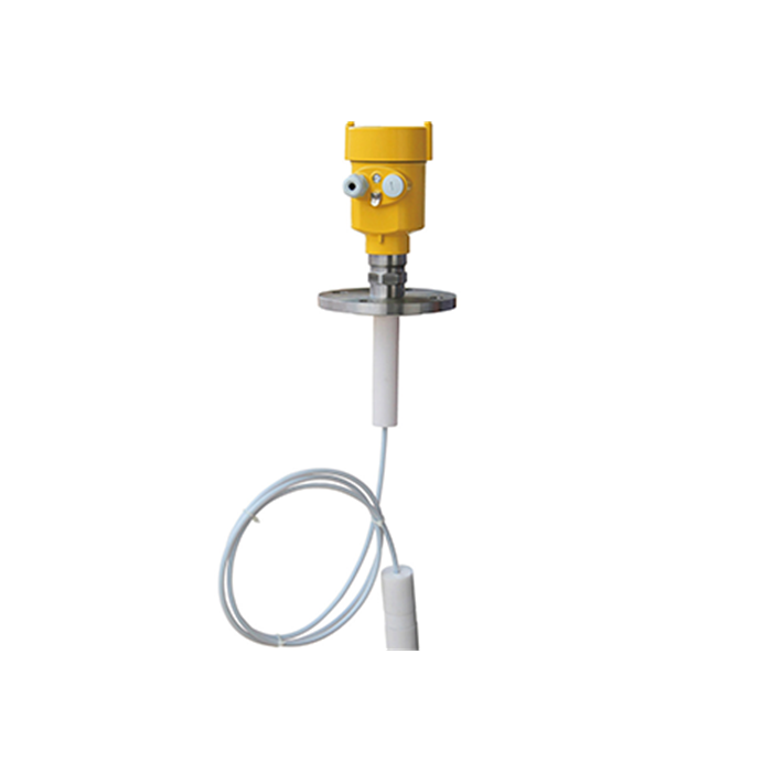
Guided-wave radar can perform well in some viscous services, but a coated probe changes the transmission path and a viscous product can exert mechanical loads during draining or agitation. Probe selection should consider removal force, cleaning and whether the process can tolerate a probe at all.
A resin example: the critical state is the shutdown
Consider an illustrative resin process held at 80 °C during production. During a weekend stop, the nozzle region cools faster than the tank and residue becomes much thicker. The level reading may be acceptable throughout production and fail only on restart.
The correct design review therefore includes:
minimum nozzle and antenna temperature during shutdown;
heat-tracing coverage, insulation and cold bridges around flanges;
whether tracing is safe for the product and the transmitter’s process-temperature limit;
startup sequence and time required to restore flow;
echo-curve and manual inspection after a real shutdown, not only during steady production.
Heat tracing is not automatically beneficial. Overheating can cure some resins, damage seals or create a hazardous condition. The process engineer must define the allowable temperature window.
Run a coat-and-drain test that produces evidence
Where the process permits, inspect the antenna or a representative probe after a defined operating interval and after emptying. Photograph the residue and record its thickness, location and texture. Repeat after the normal cleaning cycle. If the test uses a sample or trial assembly rather than the production transmitter, keep the temperature, shear and exposure representative and state the differences.
Save an echo curve before exposure, after coating and after cleaning. The useful result is not “radar works with viscous liquid.” It is “this antenna in this nozzle showed this change after this defined exposure, and the normal cleaning cycle did or did not restore the baseline.”
Cleaning questions belong in the specification
Ask whether CIP reaches the antenna or chamber, whether spray devices create direct interference, and whether the cleaning chemical attacks the process seal. For a bypass chamber, check whether the viscous product actually exchanges through the taps; a chamber can show a historical level while the vessel has already changed.
Specify access for manual cleaning only if the plant can safely isolate, depressurize and cool the equipment. “Easy to clean” is not a design requirement unless the method, interval and acceptance condition are stated.
A specification paragraph worth copying into the RFQ
“The supplier shall review product adhesion and residue formation at the antenna or probe during production, emptying, cleaning and shutdown. The review shall state the assumed residue condition, temperature limits, cleaning method and any required inspection interval. A viscosity value alone shall not be accepted as evidence of suitability.”
This paragraph does not force a particular antenna. It forces the offer to disclose its assumptions. During operation, set the first inspection from observed deposit behavior rather than an arbitrary annual date. If the antenna remains clean after several defined cycles, extend the interval through the plant’s change process; if echo quality or residue changes, investigate before extending it.
Questions from resin, syrup and bitumen applications
Q1. Is there a maximum viscosity for radar?
There is no useful universal cP limit for non-contact radar. Coating, dielectric properties, temperature and installation determine the outcome. Guided-wave probes add mechanical and coating constraints.
Q2. Should the antenna be heated?
Only with a validated design. The product’s thermal limits, seal limits, transmitter limits and area classification all matter.
Q3. What is the best proof before purchase?
A representative coating and cleaning test plus an installation drawing review. A viscosity value alone is weak evidence.
