


 Chinese
 Spanish
 Russian
 Portuguese
 French
 German
 Indonesian
 Thai
 Vietnamese
 Arabic
 Italian
 Turkish
 Polish
 Japanese


Overfill Prevention Level Measurement: Set the Independent High-High Alarm from Fill Rate
Safety principle. Overfill prevention level measurement must leave enough distance to stop the inflow after the alarm or trip occurs. A high-high switch mounted near the overflow is not adequate if pump rundown, valve closure and operator response consume the remaining space. Independence also has to be physical and functional: two numbers from one transmitter are not two layers of protection.
Calculate the setback before choosing the alarm elevation
Start with the maximum credible fill rate, not the normal pump average. Include all simultaneous inflows that the scenario permits. Then list every delay between product crossing the trip point and flow actually stopping.
Illustrative operator-response case. Maximum fill rate is 0.80 m/min. The alarm needs 5 seconds to be recognized, the operator is allocated 60 seconds to respond, and the remote valve plus pump rundown needs another 12 seconds. Total allocated time is 77 seconds, or 1.283 minutes.
Level rise after trip = 0.80 × 1.283 = 1.03 m
For the assumed constant level-rise rate and sequential delays, the response distance is about 1.03 m. Add measurement, datum, setting, wave and other required margins before choosing the maximum trip elevation. If the additional allowance is 0.35 m, the example setback is about 1.38 m below the limiting level. Include all relevant detection, logic and shutdown delays without double-counting them.
This is an example, not a universal setpoint. If inflow is specified as volume per time and vessel cross-section varies with height, derive level rise from the actual capacity curve instead of assuming one constant m/min rate. An automatic safety instrumented function has a different response chain and proof requirements; use the project hazard analysis and applicable standard.
| Time or distance allowance | Data source | Common omission |
|---|---|---|
| Maximum fill rate | Pump/valve and transfer study | Using normal rather than credible maximum |
| Sensor and logic delay | Device and logic-solver data | Assuming the trip is instantaneous |
| Human response | Written operating response analysis | Assuming an operator is always watching |
| Valve closure and pump rundown | Test or vendor dynamic data | Treating commanded closed as zero flow |
| Measurement and setting tolerance | Instrument and configuration data | Ignoring datum and alarm tolerance |
| Waves and process margin | Vessel and hazard assessment | Using all remaining height as usable margin |
Independence is a chain, not a second tag number
A control radar and an alarm switch can share a nozzle, a process seal, a power supply, a PLC input card or a common configuration tool error. Whether that is acceptable depends on the required risk reduction and the applicable overfill philosophy. Do not claim independence without listing shared elements.
For a genuinely separate high-high layer, review the sensing element, process connection where required, electronics, output, logic solver, power, final element and human procedures. A second channel in the same transmitter may provide useful diagnostics, but it is not automatically an independent protection layer.
Use a shared-cause table during the review. Rows should include product coating, blocked nozzle, loss of power, failed input card, incorrect range, common software change, bypass left active and final-element failure. Columns should show whether the control function and high-high function are both affected, how the failure is detected and what procedural response remains. This is more revealing than a drawing with two instrument bubbles.
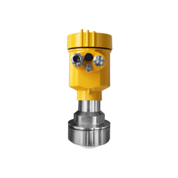
A continuous radar for control plus a point-level switch for high-high is a common architecture. A second continuous device can also be appropriate when its diagnostic coverage, installation and output chain meet the requirement. The technology label matters less than the verified failure behavior.
Normal, high and high-high are different functions
Normal high may stop a routine transfer or request operator attention. High-high is the last defined level layer before the limiting condition. If both trip the same valve through the same logic and share the same failure, their risk-reduction contribution cannot simply be added.
Also distinguish maximum operating level, alarm level, trip level, overflow elevation and structural or safe fill limit. A tank drawing that shows only “100%” is not enough to design overfill protection.
Proof testing must test the chain you rely on
A device self-test does not prove that the nozzle is clear, the switch is at the correct elevation, the logic solver acts, or the final valve stops flow. Define how much of the chain each test covers and what separate tests cover the rest.
Questions for the test procedure:
Can the physical product level be raised safely, or is an approved simulation method used?
Does simulation bypass the sensing element, and what additional inspection covers that gap?
Is the trip tested to the logic solver only, or through the final element?
Are bypasses logged, time-limited and independently restored?
Are trip elevation, setpoint, actual response time and as-left values recorded?
Is the interval derived from the safety requirements and plant evidence rather than copied from another site?
Do not claim SIL performance from a device certificate alone. The safety function, architecture, dangerous failure data, proof-test interval, common-cause assumptions and operational procedures all matter.
Questions from overfill reviews
Q1. Can the control radar’s high-high alarm be the independent backup?
Not by default. It shares the sensor and electronics. Whether any credited backup exists requires an independence and risk assessment.
Q2. Is a vibrating fork safer than radar for high-high?
Neither technology is automatically safer. Suitability, diagnostics, product behavior, installation, architecture and proof testing determine the protection provided.
Q3. Why not set high-high as close to overflow as possible?
Because inflow continues during detection, decision and shutdown. The calculated response distance and margins may require a lower setpoint.
Q4. Can a false-echo map be used as the safety basis?
The complete configuration and change control affect reliability. Safety-related settings require the project’s verification and management-of-change process; a convenient commissioning feature is not proof of safety.
Q5. What should an RFQ include?
Limiting level, proposed trip elevation, maximum fill rate, shutdown philosophy, required independence, applicable standard or category, product and nozzle data, proof-test constraints and required diagnostics.
