


 Chinese
 Spanish
 Russian
 Portuguese
 French
 German
 Indonesian
 Thai
 Vietnamese
 Arabic
 Italian
 Turkish
 Polish
 Japanese


Radar Level Transmitter for Small Tanks: The 1.5 m Span Check
Selection rule. A radar level transmitter for small tanks must be judged by its usable span, not its maximum measuring range. A device advertised for 30 m may be a poor choice for a 1.5 m vessel if its near-zone limit, antenna geometry and nozzle echoes consume the top of the tank. On a short span, a few millimetres of datum error and a few seconds of damping also become much more significant.
Work from the required levels, not the vessel height
List the bottom zero, normal low, normal high, high alarm and overflow elevations on one sketch. Then add the antenna reference, nozzle outlet, blocking distance and any stilling-well or probe limits. This sketch tells you whether the transmitter can see every level the process requires.
Worked 1.5 m tank. Suppose the antenna reference is 1.60 m above the tank bottom and the manufacturer requires a 0.20 m near-zone exclusion below that reference. The nearest product level the device can measure is therefore 1.40 m above the bottom. If the required high-high alarm is at 1.45 m, the continuous transmitter cannot provide that alarm reliably. Either the mounting/reference must change, a suitable device with a shorter near zone must be selected, or an independent point switch must cover the top.
The full scale is not 1.60 m by default. If the operating zero is 0.10 m above the bottom and working full is 1.30 m, the configured span is 1.20 m. Document all three numbers separately.
| Short-range issue | Why it grows in a small tank | Engineering response |
|---|---|---|
| Near-zone or blocking distance | It can occupy a large fraction of total height | Compare against required high and alarm levels |
| Nozzle reflection | Product begins close to fixed internal echoes | Use a validated compact antenna and nozzle geometry |
| Datum uncertainty | 10 mm is small on 30 m but significant on 1 m | Measure and control the reference carefully |
| Fast level rate | Small volume changes quickly during filling | Check device and PLC response time |
| Foam or splashing | Surface reaches the antenna region sooner | Review process conditions at maximum level |
| Vessel internals | Mixer, coil and sensor probes sit within a short beam path | Use the actual section drawing for clearance |
Accuracy, repeatability and resolution look different on a short span
A repeatability of 1 mm does not make the absolute level accurate to 1 mm. Reference conditions, antenna alignment, datum and configuration still matter. Similarly, a display resolution of 1 mm only means the number changes in 1 mm steps.
On a 1.20 m working span, a fixed 5 mm datum error is about 0.42% of span. On a 12 m span, the same error is about 0.04%. This is why small-tank projects benefit from precise reference measurements rather than more decimal places on the display.
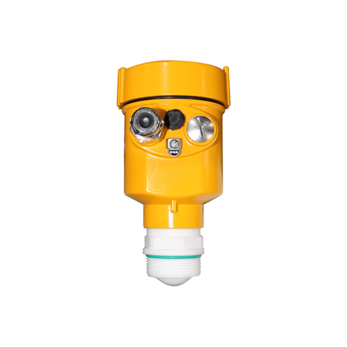
Compact non-contact radar or guided-wave radar?
Compact high-frequency non-contact radar avoids product contact and can work well with a suitable nozzle and clear near zone. Guided-wave radar can be attractive where a controlled path helps with weak reflections or restricted space, but probe bottom clearance, coating, mechanical contact and the minimum distances at both ends need review.
Do not choose guided wave merely because the tank is small. A probe touching a mixer or sitting in viscous residue creates a new maintenance problem. Conversely, do not choose non-contact merely to avoid a probe if the required high level lies inside its near-zone limit.
Compare offers on the same vessel sketch. In the 1.5 m example, “Option A: 30 m range” and “Option B: 15 m range” are not useful comparison rows. Replace them with antenna reference, manufacturer near-zone limit, highest measurable product elevation, lowest measurable elevation, accuracy at the actual range and nozzle restriction. The option with the shorter catalogue range may be the only one that covers the high alarm.
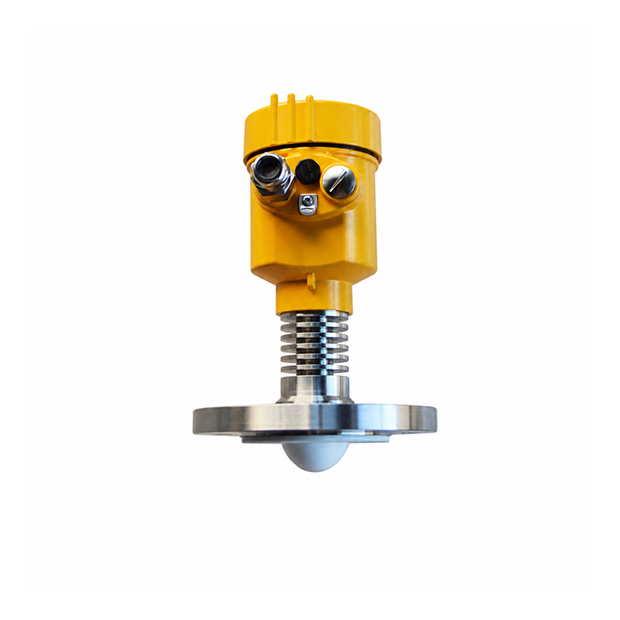
The five-minute RFQ screen
Before asking for a quotation, write down:
vessel height, diameter, top and bottom geometry;
antenna reference and nozzle inside diameter and projection;
operating zero, working full, high alarm and overflow elevations;
minimum and maximum level rates;
product, temperature, pressure, vapor, foam and cleaning conditions;
every internal within the measuring path;
required output, response time and hazardous-area approval.
A supplier who receives only “1 m tank, 4–20 mA” has to guess the very details that determine whether the instrument works.
Questions from compact-skid designs
Q1. Can the transmitter be raised above the tank to gain range?
Sometimes, but the new nozzle or standoff must preserve the antenna’s approved installation and must not move the device beyond its temperature, access or mechanical limits. Recalculate all references and alarms.
Q2. Is 80 GHz always best for a small tank?
No. Frequency alone does not specify near-zone performance, antenna size, materials or process suitability. Compare the complete model data.
Q3. Why does the level jump near the top?
The real echo may enter a near-zone or compete with nozzle reflections. Inspect the echo curve and configuration rather than adding damping.
Q4. Should a point level switch be added?
Add one when the required trip point is outside the continuous device’s reliable zone, or when independence is required by the protection philosophy.
