


 Chinese
 Spanish
 Russian
 Portuguese
 French
 German
 Indonesian
 Thai
 Vietnamese
 Arabic
 Italian
 Turkish
 Polish
 Japanese


Electroplating tank level measurement has to work with racks, heaters, extraction ducts and a chemically aggressive atmosphere. The space above an empty bath can look clear but become obstructed when a carrier moves into position. Review the instrument's mounting location through the complete production movement, not just during shutdown.
Use a plan view and a section through the bath
Show the rack travel, workpiece envelope, anodes, heaters, inlet and liquid levels. Keep the sensor outside the collision envelope and preserve access to the cover and ventilation system. Moving close to a wall to avoid a carrier may create a measurement problem farther down the tank.
Two METRAVON candidates illustrate why compact size is not the same as a narrow beam. The MV-RD11S has a 21 mm PTFE lens with a nominal 14-degree beam; the MV-RD12 has a 32 mm PTFE lens with an 8-degree beam. Compare the full path and fitting dimensions before choosing between them.
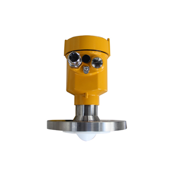
Approve electroplating tank level measurement bath by bath
Acid, alkali and rinse tanks cannot share a material approval merely because they belong to one line. Record constituents, concentration, temperature and cleaning media for each bath. Review the lens, seal, mounting metal, bracket and cable entry against splash, vapour and condensate exposure.
| Event | Level effect | Review needed |
|---|---|---|
| Rack entry | Immersed workpieces displace liquid. | Available headroom with the largest permitted load. |
| Make-up | An inlet jet disturbs the surface. | Sensor position and refill stopping response. |
| Vent change | Mist and condensate exposure can change. | Deposits at the lens and corrosion around the mount. |
| Bath service | Cleaning introduces a different chemical duty. | Material compatibility and restored mounting position. |
Set limits from equipment needs and displacement
The low operating limit may be constrained by heater coverage, circulation or pump suction. The high limit must leave room for both make-up liquid and workpiece displacement. Derive those limits with the equipment supplier and line operator; convenient percentages of tank height do not define safe operation.
Where a consequential overflow requires an independent protective function, specify it separately. The continuous radar signal should also carry a defined fault response at the PLC. A communications timeout must not silently leave make-up control relying on an apparently current level.
Questions from line maintenance
Q1. Can a protective cover be added over the antenna?
Only after reviewing its effect on the measurement and chemical exposure. An arbitrary shield can create another reflection or trap deposits. Preserve ventilation and maintenance access rather than improvising a cover after commissioning.
Q2. How should the installation be accepted?
Compare readings at safely verified levels, then observe rack movement, circulation and make-up. Record the chemical and temperature during the trial. Inspect for deposits and mist attack after representative service before setting a maintenance interval.
Q3. Why not copy settings from the adjacent bath?
The adjacent tank may have different internals, fluid, nozzle height or rack displacement. Reuse only settings that have been verified against that bath's dimensions and operating duty; retain a parameter record by tank tag.
Summary
For an electroplating application enquiry, send the bath chemistry and drawings with the rack in its limiting positions. Choose the radar after the clear measuring path, material exposure and operating limits are established.
