


 Chinese
 Spanish
 Russian
 Portuguese
 French
 German
 Indonesian
 Thai
 Vietnamese
 Arabic
 Italian
 Turkish
 Polish
 Japanese


Parabolic radar antenna replacement is not just a choice of frequency or measuring range. The existing reflector, feed, support and alignment form an assembly with a physical envelope and mounting requirements. Replacing it with a different radar design needs a review of the complete installation, not a promise that another antenna will fit the same opening.
Compare the documented antenna assemblies
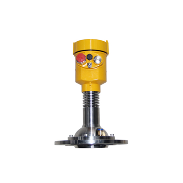
For a parabolic replacement assessment, METRAVON MV-RD904 is a documented 26 GHz parabolic-antenna model for dusty silos, with 196 mm or 242 mm reflector options. Compare the offered complete assembly with the existing opening and support drawing; the model name does not establish antenna-component interchangeability.
The METRAVON MV-RD21 is a bulk-solids radar with a 76 mm PTFE lens and a nominal 3-degree beam. It is not specified as a parabolic-antenna instrument. It may be considered as a complete alternative for a suitable silo duty only after the target, distance interval, nozzle and process conditions are reviewed.
If the enquiry requires an original-equipment antenna spare, identify the original radar and requested component. The MV-RD904 listing supports review of a complete parabolic transmitter, not a claim that its reflector or feed fits another instrument. An MV-RD21 proposal changes to a lens assembly and needs its own mounting and process review.
Identify what is being replaced
Establish whether the enquiry concerns an antenna component, the complete transmitter or the support structure as well. Obtain the original assembly drawing and model identification. Do not attach an unrelated reflector or feed to existing electronics based on appearance; compatibility must be documented for the complete instrument design.
For a different transmitter, compare the required measurement task, connection and aiming arrangement independently. A narrow nominal beam does not establish equal performance across different antenna designs, and it says nothing about whether the new assembly can be installed or maintained at the existing location.
Parabolic radar antenna replacement starts with an envelope drawing
| Review | Information needed for the complete assembly |
|---|---|
| Space | Overall dimensions, access path and clearance for removal or alignment. |
| Support | Assembly mass, mounting details and loads for the responsible structural review. |
| Exposure | Outdoor environmental conditions and any required wind-load assessment. |
| Alignment | Intended target, adjustment arrangement and method for retaining the approved orientation. |
Have the responsible designer assess support loads from documented geometry and site conditions. Wind loading, bracket capacity and mounting torque must be established for the selected assembly and site. Do not infer those values from the frequency or from a photograph of a similar installation.
Acceptance after a change of design
Record the new reference position and aiming direction after installation. Compare behaviour through representative fill and discharge conditions, including the lowest and highest required surfaces. Reusing the old bracket or configuration does not establish equivalence; an altered reference position can affect level conversion even when distance measurement is correct.
Q1. Can the old support always be reused for a smaller instrument?
No. Check connection geometry, stiffness, load transfer and available adjustment. Smaller external size is not proof of a suitable mounting interface or retained alignment.
Q2. Does the same frequency make antenna parts interchangeable?
No. The antenna and electronics are part of a defined design. Use documented compatible components, or assess a complete replacement transmitter with its own installation requirements.
Summary
Review the whole assembly before approving an antenna-related retrofit. Send the existing drawings, support details and silo duty for an MV-RD904 parabolic-transmitter review, or identify an MV-RD21 lens-radar alternative as a separate design change.
