


 Chinese
 Spanish
 Russian
 Portuguese
 French
 German
 Indonesian
 Thai
Thai Vietnamese
 Arabic
 Italian
 Turkish
 Polish
 Japanese

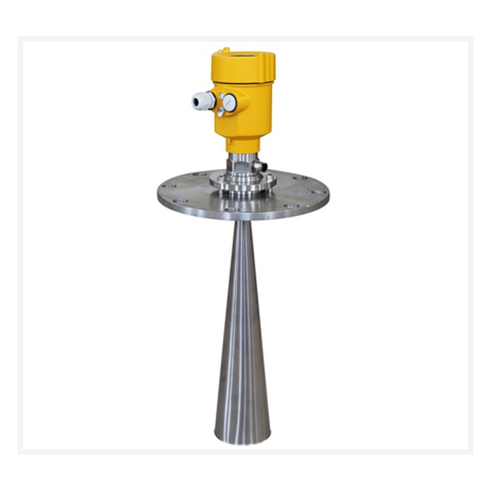
Radar level transmitters use electromagnetic waves for continuous level measurement of liquids and bulk solids. Non-contact radar does not remain immersed in the process medium and is widely used in industrial tanks, water treatment systems, chemical processes and bulk-solid silos.
Measurement stability depends on instrument selection, mounting position, vessel geometry, nozzle dimensions, filling conditions and internal structures. A well-designed mounting position reduces fixed interference echoes at the source and simplifies subsequent signal processing. Installation should therefore be based on the beam angle, antenna design and requirements of the selected radar model.
1. What Should Be Confirmed Before Installing a Radar Level Transmitter?
Before installation, confirm the process medium, maximum measuring distance, process temperature, process pressure, vessel or silo geometry and required process connection. If the vessel is in service, follow site safety procedures before opening any flange, threaded connection or process port. The vessel should be depressurized and confirmed safe from hazardous temperature, toxic, flammable or corrosive media.
Confirm Measuring Range
Determine the maximum distance from the radar mounting point to the lowest expected level.
Confirm the Medium
Liquids, slurries, powders, granules and bulk solids have different reflection characteristics.
Confirm Temperature and Pressure
Process conditions should remain within the rated limits of the selected model.
Check Internal Structures
Identify agitators, beams, coils, ladders, pipes and filling points before selecting the mounting position.
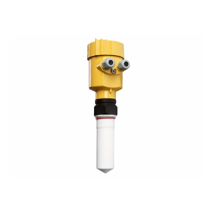
2. Where Should a Radar Level Transmitter Be Installed?
Non-contact radar is normally mounted at the top of a tank or silo. The preferred position provides a clear measurement path to the material surface while minimizing fixed structures within the main radar beam.
The distance from the vessel wall should be determined from vessel diameter, radar beam angle and internal geometry. Different frequencies and antenna designs have different beam characteristics, so the installation distance should follow the requirements of the specific model. Narrow-beam 80GHz radar often provides greater mounting flexibility in complex vessels or near-wall applications.
Avoid Filling Streams
Falling solids, incoming liquid and jets can block the true surface and generate unstable echoes.
Avoid Large Obstacles
Agitators, beams, ladders, pipes and heating coils can create fixed false echoes.
Control Wall Reflections
Select the mounting position according to beam angle and vessel geometry.
Aim at a Representative Surface
Liquid applications are normally mounted vertically; solids should consider the angle of repose.
3. Is the Center of a Tank a Suitable Mounting Position?
Suitability of center mounting depends on vessel geometry, antenna beam angle and radar design. In some cylindrical tanks, symmetrical geometry can create stronger multiple reflections around the center, so certain wider-beam radar designs are commonly installed off-center.
Modern narrow-beam high-frequency radar provides greater installation flexibility, and center mounting can also work in selected applications. The final position should follow the vessel geometry and the installation requirements of the selected model.
4. How Should a Flange Orientation Mark Be Positioned?
Some radar transmitters include an orientation mark on the flange, threaded connection or housing because the antenna has a defined polarization direction. Depending on the product design, the mark may need to align with the vessel wall, a stilling-well opening or a bypass connection.
The orientation mark should be positioned according to the installation instructions of the specific model so that antenna polarization matches the vessel geometry and fixed reflections are minimized.
5. What Should Be Considered for Threaded and Flanged Mounting?
Threaded and flanged connections are both widely used for radar level transmitters. After installation, the antenna should maintain the required orientation and the process connection should provide suitable sealing for the process medium, temperature and pressure.
For models with orientation requirements, antenna direction can be optimized during commissioning by observing the echo curve or echo strength. Any flange or threaded adjustment should be performed under safe process conditions and according to the applicable maintenance procedure.
6. What Should Be Considered When Installing Radar on a Nozzle?
Radar transmitters are often installed on a short process nozzle at the top of a vessel. The nozzle becomes part of the radar signal path. A nozzle that is too long, too narrow or places the antenna too deeply inside can create additional reflections and reduce useful echo strength.
Nozzle dimensions should be selected according to antenna size, operating frequency and the specific radar model. A suitable nozzle structure improves beam propagation and reduces fixed reflections from the nozzle wall.
| Nozzle Item | General Guidance |
|---|---|
| Nozzle Diameter | Select according to antenna dimensions and the product datasheet |
| Nozzle Length | Keep as short as practical; maximum allowable length depends on diameter and antenna type |
| Antenna Position | Some models require the antenna to extend beyond the nozzle; confirm for the specific product |
| Nozzle Interior | Keep the internal surface smooth and minimize large welds, steps, burrs or other strong reflectors |
7. How Should Radar Be Installed in a Bulk-Solid Silo?
Bulk solids generally form a sloped surface and may create moving piles, dust and irregular geometry during filling. Radar installation should therefore consider the filling direction, material angle and internal silo structures.
The radar is normally positioned where it can represent the average material level and remain outside the main filling stream. Large or tall silos may use an adjustable flange or aiming arrangement so that the radar beam is directed toward the preferred measurement area.
Because 80GHz radar provides a narrow beam, it often offers installation advantages in silos with structural beams, wall features or complex material surfaces. Dust concentration, measuring range and material reflectivity should still be considered during selection.
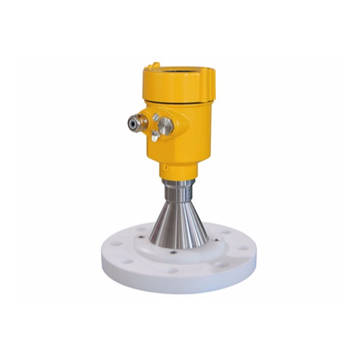
8. How Do Internal Obstacles Affect Radar Measurement?
Radar signals can be reflected not only by the process surface but also by vessel walls, beams, agitators, heating coils, ladders and other metallic structures. Strong fixed echoes can interfere with identification of the actual level signal.
Installation design should keep major fixed structures outside the primary beam where practical. If some structures remain unavoidable, false-echo suppression or echo-learning functions can be used to further optimize measurement.
9. What Is False-Echo Suppression?
False-echo suppression is a common commissioning function in modern intelligent radar level transmitters. During setup, the instrument can record reflections generated by fixed internal structures and reduce their influence during normal operation.
The actual process level should be known during echo learning, and the learning range should be configured appropriately so that the true material echo is not stored as a fixed interference signal. False-echo suppression should be used on the basis of a suitable mounting position.
10. Do Foam, Surface Movement and Agitation Affect Radar?
Foam, strong surface movement and agitation can change the strength and stability of radar echoes. Radar generally adapts well to variations in air temperature and gas-phase conditions, but the condition of the process surface should still be considered during selection and commissioning.
Thick foam can absorb or reflect part of the radar signal. Its effect depends on foam thickness, water content, medium properties, radar frequency and antenna design. Persistent foam applications may be evaluated using different radar frequencies, guided wave radar or other level technologies.
For strongly agitated surfaces, the radar should be installed away from agitators and inlet-impact zones, with damping and filtering configured according to the required process response.
11. Why Are Low-Dielectric Media More Difficult to Measure?
Radar echo strength is related to the dielectric properties of the medium. Low-dielectric materials generally generate weaker surface reflections and therefore require suitable radar dynamic range and signal processing capability.
At very low liquid levels, part of the radar energy may continue through a low-dielectric liquid and generate a reflection from the tank bottom. Actual measurement behavior depends on dielectric properties, liquid depth, tank-bottom geometry and the radar signal-processing algorithm.
12. Why Do Conical or Curved Tank Bottoms Require Special Attention?
Conical, curved and other irregular tank bottoms change the reflection direction of radar signals. When the liquid level approaches the bottom, the relative strength of the liquid-surface echo and tank-bottom echo may change, so measurement behavior at very low level can differ from normal operating levels.
Tank height, zero point and related vessel parameters should be configured correctly during commissioning. Where a process requires independent very-low-level protection, a separate level switch may be used as an additional protective layer alongside continuous radar measurement.
13. When Should a Stilling Well, Bypass Chamber or Guided Wave Radar Be Used?
Applications with complex internal structures, strong surface movement or special mounting constraints may use a stilling well, bypass chamber or guided wave radar according to the process conditions.
Stilling Well
Suitable for selected liquid applications where a more stable measurement path is required. Pipe diameter, opening design and radar compatibility should be matched.
Bypass Chamber
Suitable for selected process vessels and can isolate the measurement zone from severe surface movement in the main tank.
Guided Wave Radar
Guides the radar signal along a rod or cable and is suitable for selected foam, interface, low-dielectric and bypass applications.
Stilling wells, bypass chambers and guided wave radar have different application conditions and should be selected according to viscosity, buildup, process temperature, pressure and maintenance requirements.
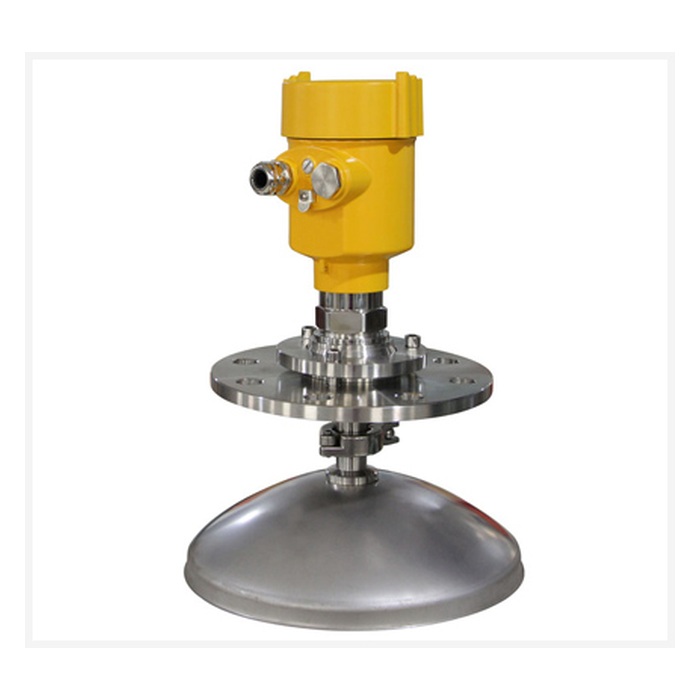
14. What Else Should Be Considered for Outdoor Radar Installation?
Outdoor installation requires attention to enclosure protection, cable routing and electrical safety in addition to the measurement position. Cable glands should match the cable diameter and be correctly tightened. A drip loop is recommended for outdoor cable entry to reduce the risk of rainwater traveling along the cable toward the instrument.
Where required by the environment, the radar housing can use suitable shading or mechanical protection. Lightning-prone locations should include appropriate grounding and surge protection as part of the site electrical design.
15. Radar Level Transmitter Installation Checklist
| Inspection Item | Information to Confirm |
|---|---|
| Process Medium | Liquid, slurry, powder, granules or bulk solids, including dielectric properties |
| Measuring Range | Maximum distance from the sensor to the lowest expected level |
| Mounting Position | Keep filling streams, agitators and major fixed structures outside the primary beam |
| Distance from Vessel Wall | Determine according to vessel diameter, beam angle and product installation requirements |
| Nozzle | Diameter and length comply with the selected radar model |
| Process Temperature | Remain within the rated operating range |
| Process Pressure | Remain within the rated pressure range of the process connection and instrument |
| Internal Structures | Identify beams, coils, ladders, piping and agitators |
| Difficult Process Conditions | Confirm foam, vapor, condensation, dust, surface movement and buildup |
| Output Interface | 4–20mA, HART, RS485 Modbus RTU or other required interface |
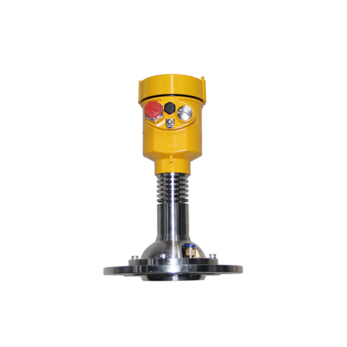
FAQ
Q1: How far should a radar level transmitter be installed from the vessel wall?
A1: The required distance depends on radar frequency, antenna beam angle, vessel diameter and internal structures. Narrow-beam 80GHz radar generally provides greater near-wall installation flexibility. The final distance should follow the selected model's installation requirements.
Q2: Can a radar level transmitter be installed in the center of a tank?
A2: The suitability of center mounting depends on vessel geometry and radar design. Symmetrical cylindrical tanks can generate multiple reflections, while modern narrow-beam radar can operate successfully in selected center-mounted applications.
Q3: Should radar always be mounted perpendicular to the liquid surface?
A3: In normal liquid applications, the antenna should generally face the average liquid surface directly. Bulk-solid applications should consider the angle of repose, filling position and required beam direction.
Q4: Why should the mounting position avoid the filling point?
A4: Falling solids or incoming liquid can enter the radar beam and block the true process surface, creating unstable reflections. The preferred mounting position is normally outside the filling stream.
Q5: What should be considered when radar is installed on a long nozzle?
A5: Nozzle diameter and length should comply with the requirements of the specific radar model. A suitable nozzle design helps reduce additional reflections and maintain useful echo strength.
Q6: How should radar be selected for foam applications?
A6: Selection should consider foam thickness, water content, process-medium properties and radar frequency. Persistent thick foam may require comparison of different radar frequencies, guided wave radar or other level technologies.
Q7: When is false-echo learning useful?
A7: It is useful when beams, pipes or other unavoidable fixed structures generate reflections. False-echo learning should be performed after the instrument has been installed in an appropriate position.
Q8: Does radar in a bulk-solid silo need to be tilted?
A8: It depends on silo geometry and the material surface. Large silos or strongly sloped surfaces may use adjustable mounting to optimize beam direction.
Conclusion
Long-term radar level measurement stability depends on mounting position, beam angle, nozzle dimensions, internal structures, medium reflectivity and commissioning parameters. Vessel-wall distance, flange orientation and nozzle dimensions should therefore be determined according to the operating frequency, antenna design and installation requirements of the selected radar model.
Installation design should provide a clear measurement path and keep filling streams, agitators and major fixed structures outside the primary beam wherever practical. Fixed reflections that remain can be further managed through false-echo suppression. Foam, low-dielectric media, bulk-solid surfaces and tank-bottom geometry should be considered during the selection stage.
METRAVON radar level measurement products can be selected and configured according to process medium, measuring range, vessel geometry, process temperature, process pressure, foam, dust, condensation and required output interface, providing stable, compatible and scalable level measurement for industrial tanks, process vessels and bulk-solid silos.
