


 Chinese
 Spanish
 Russian
 Portuguese
 French
 German
 Indonesian
 Thai
Thai Vietnamese
 Arabic
 Italian
 Turkish
 Polish
 Japanese

Radar Level Transmitter Installation, Commissioning and Operation Guide
Radar level transmitters use electromagnetic waves to measure the distance between the sensor and the material surface, then convert this distance into liquid or bulk-solid level according to the configured reference height. Non-contact radar can be applied to water, oils, chemicals, slurries, powders, granules and other bulk materials without requiring the sensing element to remain immersed in the process.
Long-term measurement stability depends on instrument selection, mounting position, vessel geometry, medium reflectivity and commissioning parameters. A suitable mounting arrangement reduces fixed interference echoes, while correct range, empty/full adjustment, damping and false-echo settings improve measurement reliability under actual process conditions.
1. How Does a Radar Level Transmitter Work?
The radar antenna transmits electromagnetic waves toward the process surface. The waves are reflected by the liquid or solid surface and received by the antenna. The instrument calculates the distance to the material from signal travel time or, in FMCW radar, from the frequency difference between transmitted and received signals.
Level = Reference Height − Distance from Radar to Material Surface
Radar does not depend on the speed of sound in air and can operate in vacuum conditions. It generally adapts well to normal variations in air temperature, pressure and airflow. Actual performance still depends on dielectric properties, antenna design, vapor, foam, condensation and installation geometry.
2. What Process Information Should Be Confirmed Before Installation?
Process Medium
Identify whether the application involves liquid, slurry, powder, granules or bulk solids.
Maximum Measuring Distance
Determine the maximum distance from the sensor mounting point to the lowest expected level.
Temperature and Pressure
Process conditions should remain within the rated limits of the selected instrument.
Vessel Geometry
Identify vessel diameter, height, nozzle, agitators, beams, coils, ladders and filling points.
For vessels already in service, any flange, threaded connection or process opening should be handled according to site safety procedures. Pressure, high temperature and hazardous process media should be safely isolated before installation or maintenance work begins.
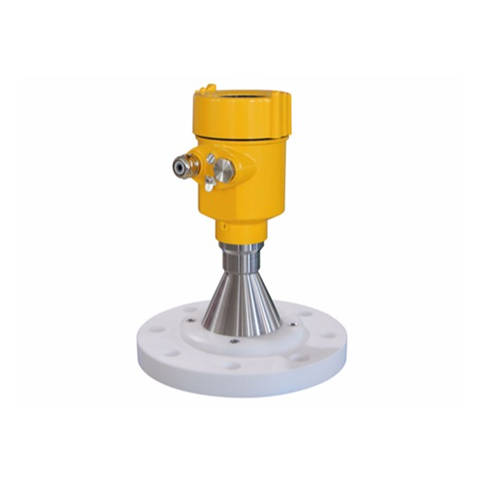
3. Where Should a Radar Level Transmitter Be Mounted?
Non-contact radar is normally mounted at the top of a vessel or silo. The preferred position provides a clear path between the antenna and material surface while minimizing fixed structures inside the main radar beam.
Distance from the vessel wall depends on radar frequency, antenna size, beam angle and vessel geometry. Wider-beam radar may require greater wall clearance, while narrow-beam 80GHz radar often provides greater flexibility near vessel walls. The final mounting position should follow the beam characteristics and installation requirements of the selected model.
Avoid Filling Streams
Incoming liquid, jets and falling solids can block the true material surface and create unstable echoes.
Avoid Fixed Obstacles
Beams, piping, heating coils and agitators can create fixed interference echoes.
Maintain a Clear Beam Path
Keep the main radar beam as clear as practical to reduce unwanted reflections.
Use Stable Mounting
Flanges, threads and mounting brackets should remain rigid and maintain antenna orientation.
4. Is Center Mounting Suitable?
The suitability of center mounting depends on vessel geometry and radar beam characteristics. Symmetrical round or domed vessels may generate stronger multiple reflections near the center, so some wider-beam radar applications use an off-center position.
For vessels with conical bottoms, center mounting can be advantageous in selected applications because the radar beam can reach the lowest part of the vessel more directly. Modern narrow-beam radar also provides greater flexibility, so the final position should be selected according to the vessel and radar model.
5. What Should Be Considered for Nozzle Installation?
Radar instruments are often installed on a short process nozzle. Nozzle diameter, length and antenna position can influence signal propagation. Long or narrow nozzles, or internal welds and steps, can generate additional reflections.
| Nozzle Item | General Requirement |
|---|---|
| Diameter | Select according to antenna size, radar frequency and the product datasheet |
| Length | Keep as short as practical; allowable length depends on diameter and antenna design |
| Antenna Position | Some models require the antenna face to extend beyond the nozzle |
| Internal Surface | Keep smooth and minimize weld beads, steps, burrs and other strong reflectors |
6. How Does Installation Differ for Liquids and Bulk Solids?
For conventional liquid applications, the radar antenna is normally directed as perpendicular as possible to the average liquid surface so that the reflected signal returns efficiently to the antenna.
Bulk-solid surfaces are usually sloped. The mounting position and antenna direction should therefore consider the filling point, outlet, silo height and expected material surface. Large silos may use an adjustable flange or aiming arrangement to direct the beam toward a representative measurement area.
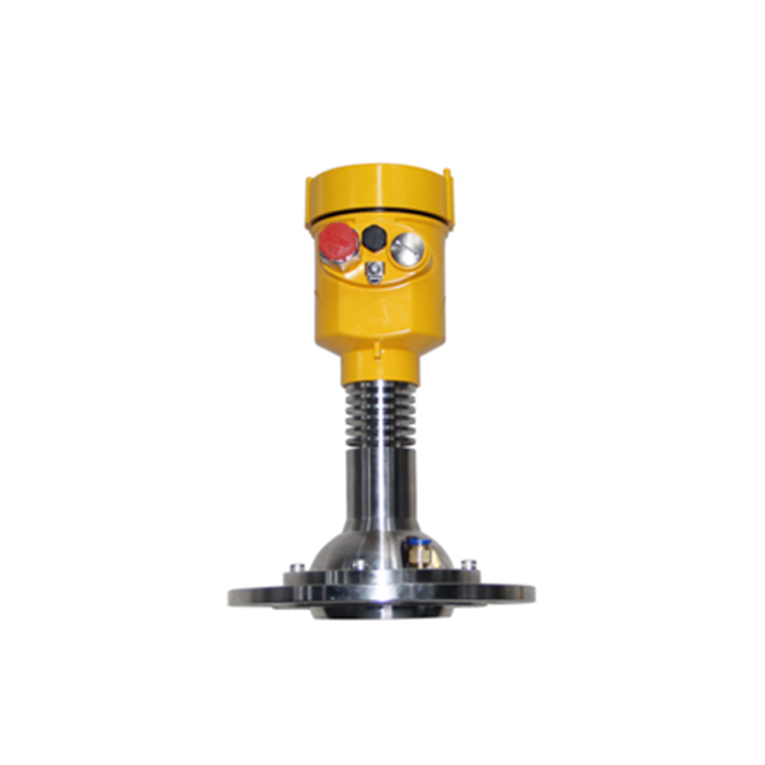
7. What Should Be Considered for Low-Dielectric Media?
Radar echo strength is related to the dielectric properties of the medium. Low-dielectric liquids generally provide weaker surface reflections, so suitable radar dynamic range, antenna design and signal processing are important.
At low level, part of the radar energy may continue through the liquid and generate an echo from the tank bottom. Measurement behavior therefore depends on dielectric properties, liquid depth, tank-bottom geometry and instrument processing. Medium type, vessel height and bottom configuration should be set correctly during commissioning.
8. How Should Foam, Surface Movement and Agitation Be Handled?
Foam, strong surface movement and agitation can change radar echo strength and stability. The effect of persistent foam depends on foam thickness, water content, medium characteristics, radar frequency and antenna design.
For dynamic liquid surfaces, the preferred mounting position is away from agitators, filling impact zones and severe turbulence. Damping and filtering should then be configured according to the actual process response requirement. Special foam applications may require comparison of different radar frequencies or guided wave radar.
9. What Commissioning Methods Are Available?
Commissioning methods depend on the radar model and communication interface. Industrial transmitters may support one or more of the following methods:
Local Display and Buttons
Used to configure measuring range, medium type, damping and output parameters.
PC Configuration Software
Useful for echo-curve analysis, diagnostics and detailed parameter configuration.
Digital Communication
HART or RS485 Modbus RTU models can support parameter reading and configuration through compatible tools.
Handheld Configuration Tools
Selected HART and industrial communication versions can be commissioned using compatible handheld communicators.
10. Which Parameters Should Be Set During Initial Commissioning?
| Commissioning Parameter | Function |
|---|---|
| Reference Plane | Defines the starting reference for distance measurement, often related to the flange sealing surface or specified sensor reference point |
| Empty / 0% Adjustment | Defines the distance from the sensor to the lowest measuring point |
| Full / 100% Adjustment | Defines the distance from the sensor to the highest measuring point |
| Medium Type | Helps optimize signal processing for liquids, solids and different echo conditions |
| Vessel Parameters | Includes vessel height, tank-bottom geometry and other model-dependent information |
| Damping / Response Time | Balances measurement response speed and output stability |
| Output Scaling | Maps 4–20mA or another output to the configured 0–100% measuring range |
| Communication Parameters | RS485 versions require device address, baud rate and applicable Modbus settings |
| False-Echo Suppression | Reduces interference from vessel walls, beams, pipes and other fixed structures |
11. Does Empty and Full Adjustment Require an Actually Empty or Full Tank?
Modern radar level transmitters can generally be configured using known installation dimensions. The tank does not necessarily need to be completely emptied or filled to perform the initial 0% and 100% adjustment.
The installer can enter the known distance from the reference plane to the lowest and highest measuring points, then verify the configured values against actual process levels during commissioning.
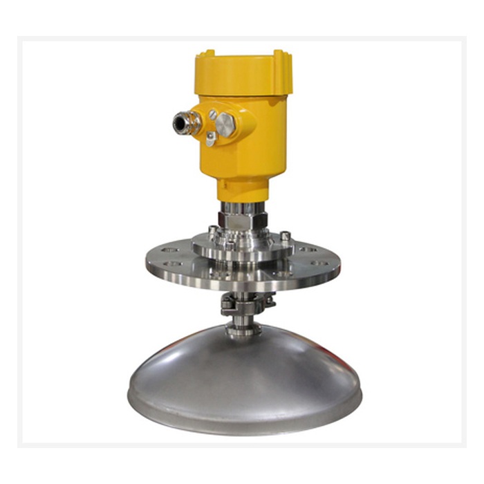
12. What Is False-Echo Learning?
Vessel walls, nozzles, beams, pipes, agitators and other fixed structures can generate radar reflections. False-echo learning records these stationary reflections and reduces their influence during normal measurement.
The actual process level should be known during the learning process, and the learning range should be set according to the product instructions so that the true level echo remains correctly identified. A suitable mounting position provides the foundation for effective false-echo suppression.
13. What Should Be Verified After Commissioning?
Displayed level corresponds to the actual level
Distance or ullage value is reasonable
4–20mA output matches the configured range
HART or RS485 communication is stable
High/low alarm or relay functions operate correctly where applicable
Echo curve does not show dominant unexpected fixed reflections
Measurement should preferably be checked at several process levels rather than at only one point. Long-term applications can also use PLC, DCS or SCADA trend data to confirm that the measured level follows actual process changes.
14. Common Operating Problems and Inspection Points
| Observed Condition | Possible Cause | Inspection Direction |
|---|---|---|
| Reading Jumps | Fixed obstacles, surface movement or false echoes | Check mounting position, echo curve and false-echo settings |
| Abnormal Low-Level Reading | Low-dielectric medium or tank-bottom echo | Check medium parameters, vessel height and bottom geometry |
| Echo Loss at High Level | Near-range interference, nozzle reflection or antenna contamination | Inspect near-range structures, antenna position and contamination |
| Unstable Bulk-Solid Level | Sloped surface, dust or multiple reflections | Optimize orientation, medium settings and filtering |
| Long-Term Drift or Instability | Antenna buildup, condensation or mounting changes | Inspect antenna condition, mounting structure and echo status |
15. Routine Operation and Maintenance
Non-contact radar has no mechanical moving parts continuously exposed to the process medium, so routine maintenance requirements are generally low. Long-term operation should still include periodic inspection of antenna buildup, condensation, cable sealing, mounting structure and output-signal condition.
Dusty, sticky or condensation-prone applications can use inspection and cleaning intervals based on the actual buildup rate. Important configuration parameters such as range, medium type, damping, output scaling and communication settings can also be backed up for future maintenance and recovery.
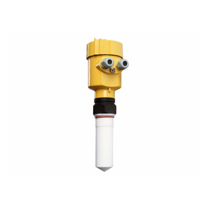
FAQ
Q1: How far should a radar level transmitter be mounted from the vessel wall?
A1: The distance depends on beam angle, antenna design, vessel diameter and internal obstacles. Narrow-beam 80GHz radar generally provides greater near-wall installation flexibility.
Q2: Does radar commissioning require an empty tank?
A2: Initial range settings can generally be entered from known installation dimensions, followed by verification against the actual process level.
Q3: Which parameters are normally required during commissioning?
A3: Typical parameters include measuring range, empty and full distances, medium type, vessel parameters, damping, output scaling and communication settings.
Q4: Why can a radar transmitter show a false level?
A4: Vessel walls, beams, agitators, piping and nozzles can generate fixed reflections. Suitable mounting and false-echo suppression help distinguish these signals from the actual level echo.
Q5: Can radar measure liquids with foam?
A5: Performance depends on foam thickness, water content, medium properties and radar frequency. Persistent thick foam should be evaluated during product selection.
Q6: What can cause abnormal readings at low level?
A6: Low-dielectric liquids may provide weak surface echoes while tank-bottom reflections become more significant. Medium type, vessel height, bottom geometry and echo curves should be checked.
Q7: What settings are required for an RS485 radar transmitter?
A7: In addition to measurement parameters, Modbus device address, baud rate and applicable communication settings should be configured and the required registers verified.
Q8: How can the installer confirm that the mounting position is suitable?
A8: Evaluate the actual level reading, echo curve, signal strength and stability at different process levels. A strong process echo with limited fixed interference generally indicates a suitable mounting arrangement.
Conclusion
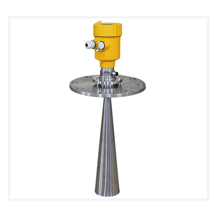
Correct installation and commissioning provide the foundation for reliable radar level measurement. Mounting design should consider vessel geometry, beam angle, filling position, nozzle dimensions and internal structures. Commissioning should then establish the correct range, empty/full points, medium type, damping, output scaling and communication settings.
Low-dielectric media, foam, strongly moving surfaces, bulk-solid silos and complex vessel structures may require additional optimization using echo-curve analysis and false-echo suppression. After commissioning, actual level, analog output, digital communication and trend data should be verified to confirm system performance.
METRAVON radar level measurement products can be configured according to process medium, measuring range, process temperature, process pressure, vessel geometry and automation interface requirements, supporting integration with PLC, DCS, RTU and remote monitoring systems for stable and scalable industrial level measurement.
